
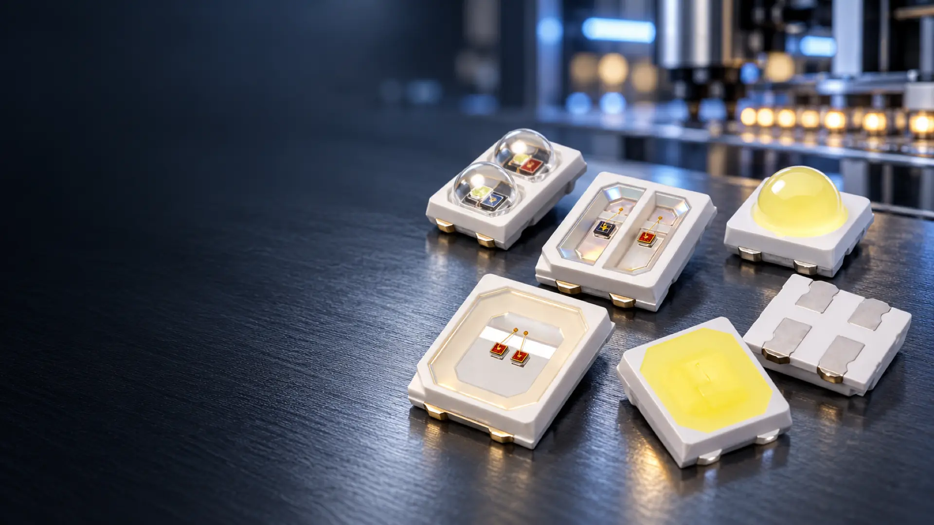
2835 SMD LED Manufacturer for Custom Wavelength and Multi-Chip Packages
Select visible colors, white, red and infrared, UV and violet, RGB or horticulture spectra in flat, dome, single-chip and multi-chip structures. Coordinate the LED package with PCB, FPC and PCBA light-source requirements when the project extends beyond the individual component.
- Visible, UV and infrared wavelength options
- Single-chip and multi-chip package structures
- Flat, cup and dome package directions
- Package-to-board integration support
Choose the 2835 Configuration That Fits the Design
The 2835 outline is only the starting point. Select the emitting spectrum, package form, chip arrangement and electrical conditions required by the finished light-source system.
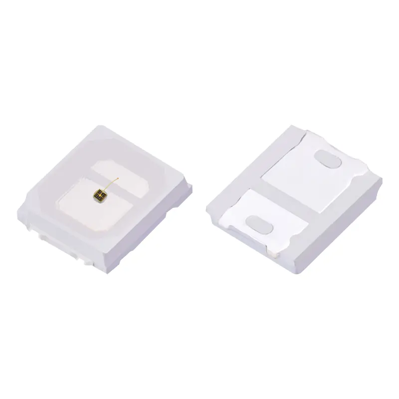
2835 Single-Color Visible LEDs
Visible-color options for indicators, specialty illumination and wavelength-specific assemblies. Available directions include red, yellow, orange, blue and green, with flat or dome packages and single- or dual-chip structures.
View Visible-Color Options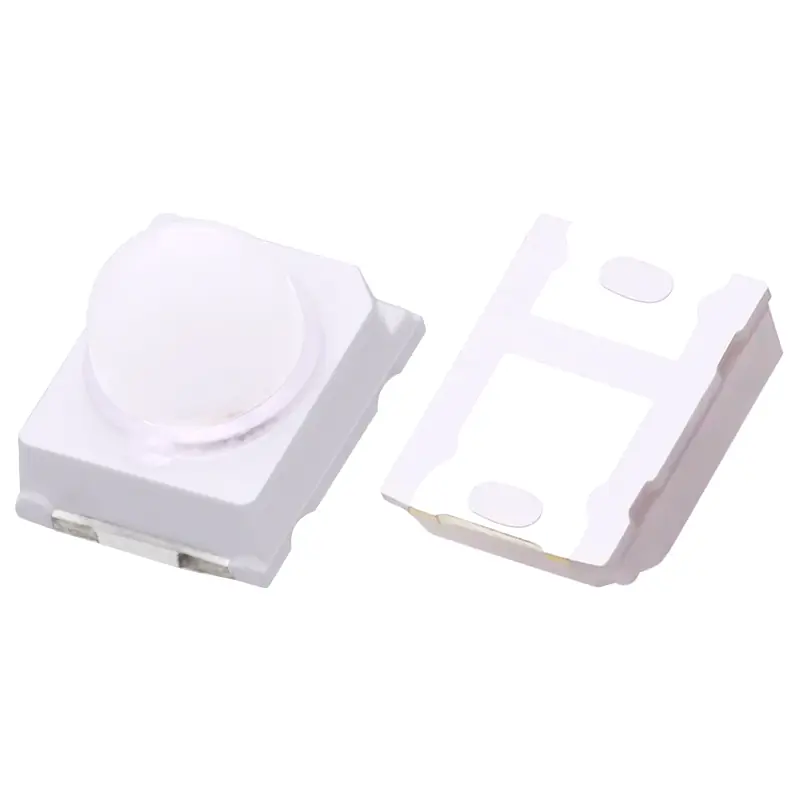
2835 White and Dual-CCT LEDs
Single-white and dual-CCT configurations for projects that require defined color-temperature options. Representative dual-white examples include 2800–3200 K and 6000–6500 K channels.
Ask About White and Dual-CCT Options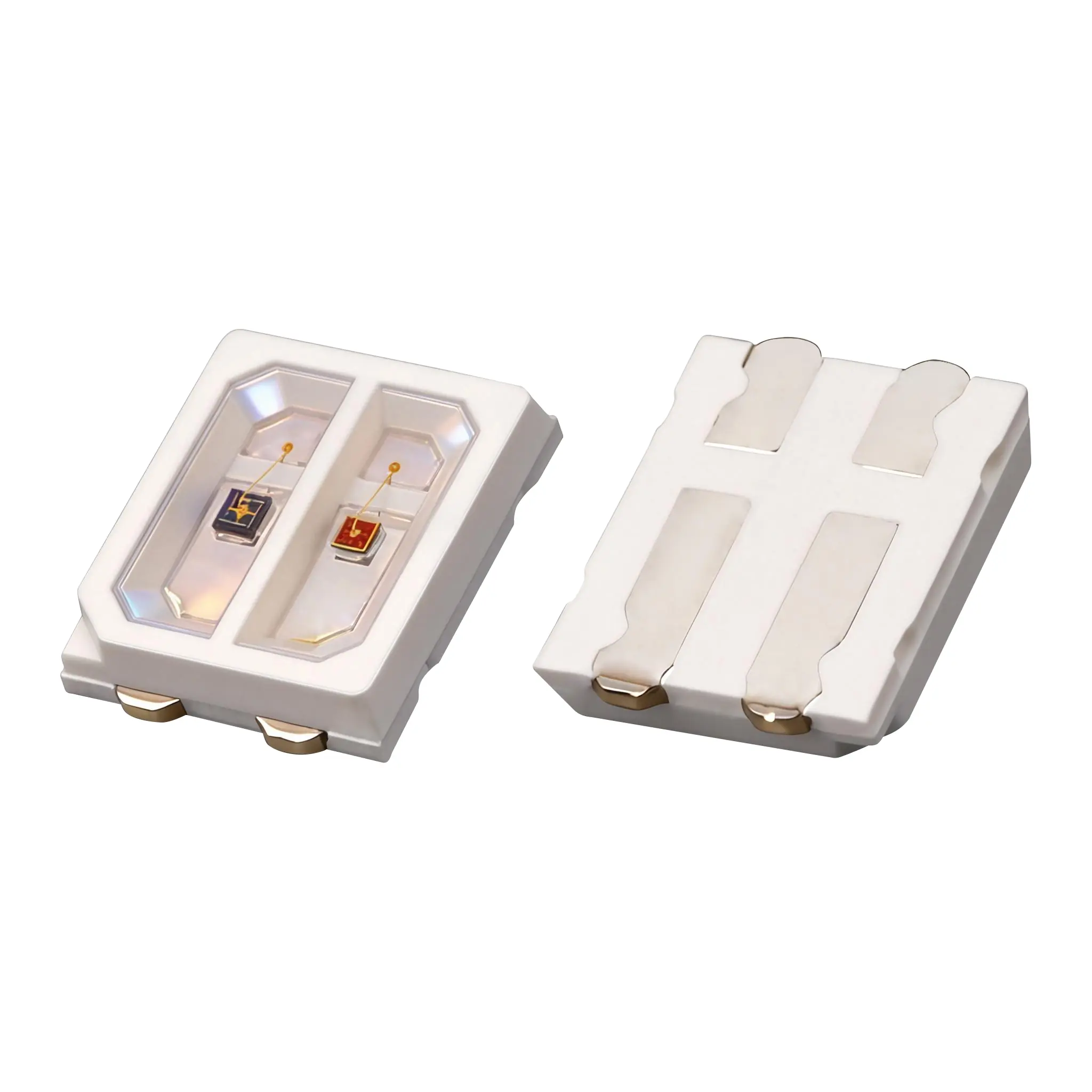
2835 Red and Infrared LEDs
Red, near-infrared and red-plus-infrared arrangements for sensing, machine-vision and device light-source designs. Flat and dome options support single- or multi-channel layouts.
View Red and Infrared Options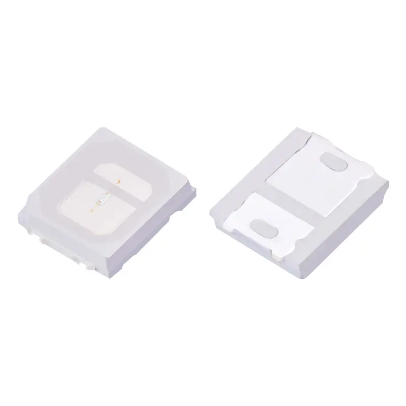
2835 UV and Violet LEDs
Violet and UVA configurations for wavelength-specific illumination and curing-related designs. Cataloged examples cover 365–375, 380–390, 390–400 and 400–410 nm.
View UV and Violet Options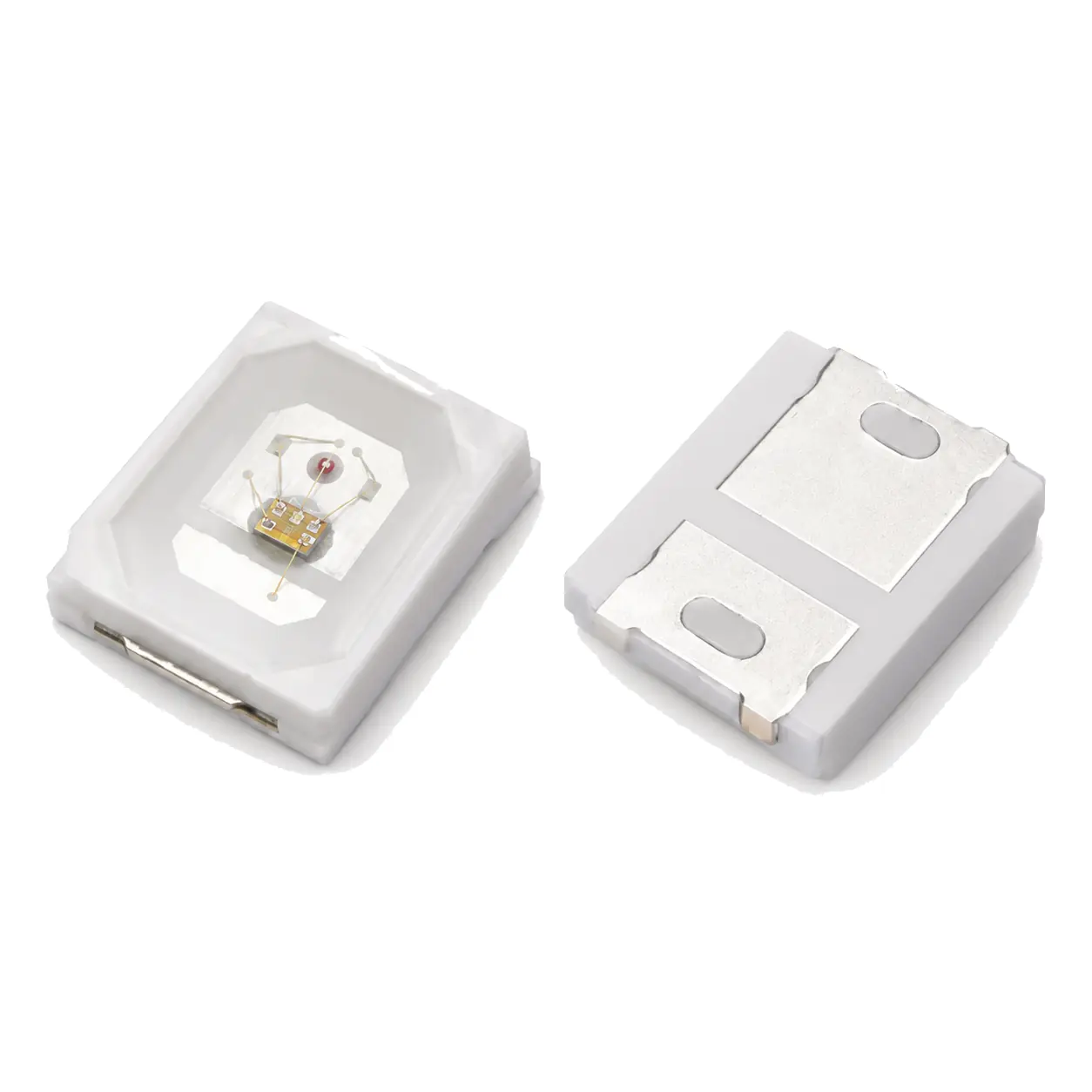
2835 RGB and Multicolor LEDs
Three-channel red, green and blue packages in flat, cup and dome constructions, with cataloged options available with or without an integrated control IC.
Ask About RGB Configurations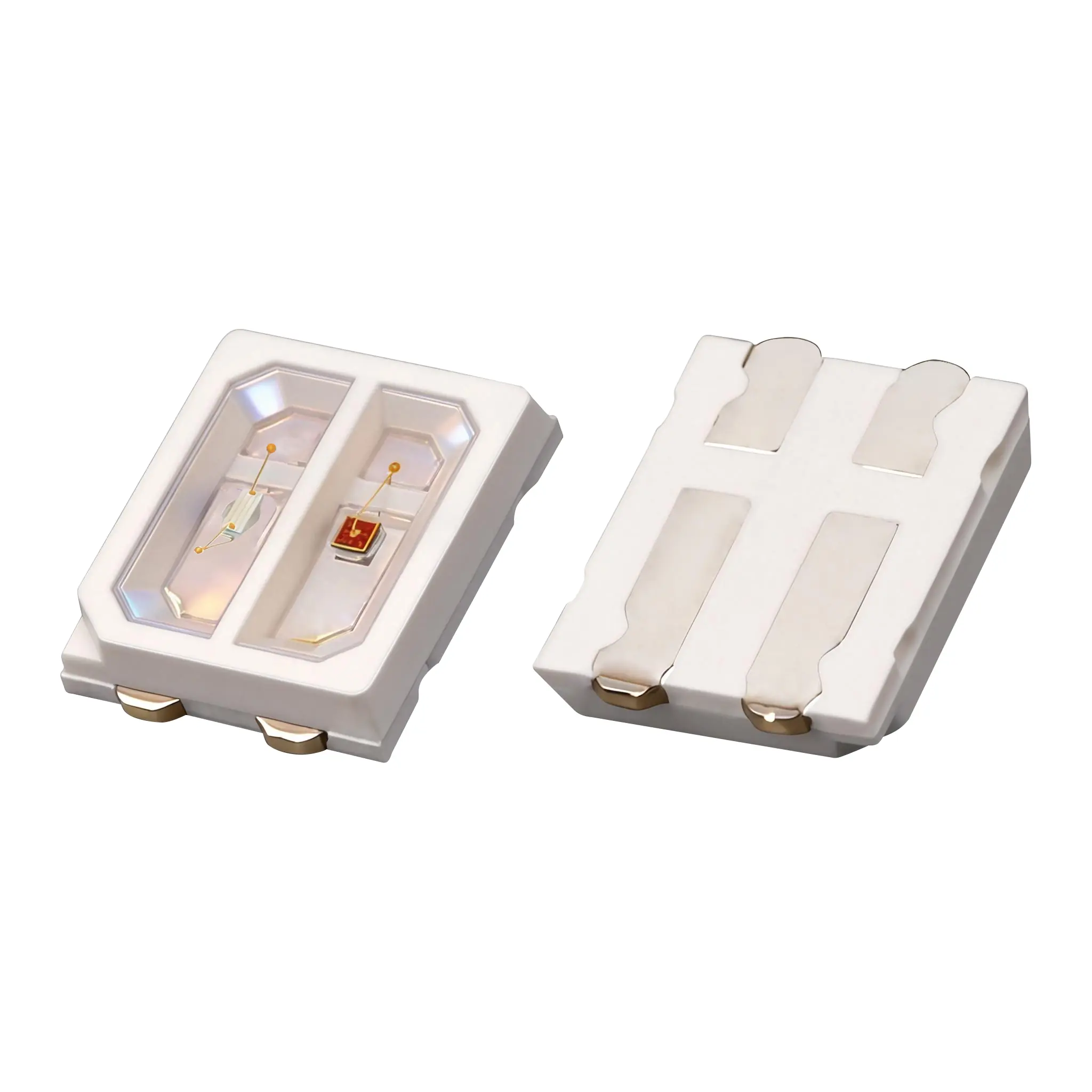
2835 Horticulture Spectrum LEDs
Red, blue, red-plus-blue and custom spectrum combinations for horticulture light-source designs. Confirm the exact spectrum, channel layout and electrical conditions by part document.
View Horticulture Options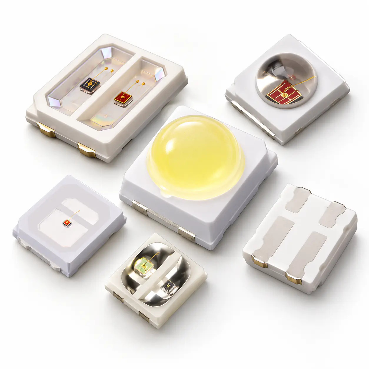
What Does 2835 Mean?
2835 identifies a surface-mount LED package with nominal outer dimensions of approximately 2.8 × 3.5 mm. It does not define wavelength, wattage, voltage, brightness, beam angle or chip count.
Do Not Treat the Package Code as a Complete Part Number
- The same 2835 outline can contain different colors, wavelengths, chip quantities and internal connections.
- Visible-light output is normally evaluated with photometric values such as luminous flux, while UV and infrared devices require radiometric values such as radiant power.
- The LED, driver, PCB or FPC layout and thermal path must be reviewed as one system.
Select and approve the exact part by its drawing, electrical conditions, optical data and sample—not by the 2835 name alone.
Representative Cataloged 2835 Configurations
The examples below show the range of configurations available within the 2835 platform. They are reference configurations rather than a universal specification for every 2835 part.
| Product direction | Cataloged electrical example | Cataloged optical example | Package direction |
|---|---|---|---|
| Visible single-color | 0.2 W, 60 mA | Blue 450–460 nm; green 520–530 nm; yellow 580–590 nm; orange 600–610 nm | Flat or dome; single- or dual-chip options |
| Red and infrared | 0.2 W or 0.5 W; 150 mA | Red 655–665 nm; infrared 845–855 nm; selected red-plus-IR or red-plus-blue combinations | Flat or dome; single- or multi-channel arrangements |
| UV and violet | 0.5 W at 150 mA or 1 W at 350 mA | 365–375, 380–390, 390–400 or 400–410 nm | Flat UV and violet configurations |
| White and dual CCT | 0.2 W, 60 mA, 2.8–3.4 V | Representative 2800–3200 K and 6000–6500 K channels | Single-white and dual-white structures |
| RGB | 0.2 W at 20 mA × 3 or 0.5 W at 50 mA × 3 | Red 620–630 nm; green 520–530 nm; blue 460–470 nm | Flat, cup or dome; with or without IC |
These are verified catalog examples, not a complete series specification. Final electrical, optical and mechanical values must follow the approved part number, datasheet and sample.
Define the Optical Target Before Choosing the Package Structure
Specify the Emission
State the target wavelength range, visible color or white-light CCT. For multi-channel designs, identify every required channel.
Choose the Package Form
Use the flat form where a broad distribution and low package profile are preferred. Consider a dome structure where the optical design requires a more directed beam. Confirm the actual viewing angle on the exact part document.
Define the Chip Layout
Choose single-chip, dual-chip or three-channel arrangements according to the required spectrum, independent channel control and available circuit layout.
Match the Electrical Design
Confirm forward voltage, forward current, series and parallel topology, driver headroom, total load and thermal path under the intended operating conditions.
Review the Part & Board
Check package outline, polarity, recommended pads, PCB or FPC layout and assembly conditions before approving the part.
Configure the Package Around the Finished Light Source
The practical value of a 2835 platform comes from selecting the emitter, package structure and board conditions together.
Multiple Emission Directions
The current range covers visible colors, white and dual CCT, red and infrared, UV and violet, RGB and horticulture spectrum directions. This provides a defined starting point before a project moves into a custom combination.
Flat, Dome and Multi-Chip Structures
Single-chip, dual-chip and three-channel layouts are available across flat, cup or dome package directions. The exact structure is selected according to the required spectrum, channel control, optical direction and available assembly space.
Package-to-Board Coordination
The LED package can be reviewed together with PCB or FPC layout, SMT assembly and PCBA light-source requirements. This keeps pad geometry, polarity, electrical conditions and channel layout connected to the finished assembly.
Part-Level Specification Review
The final selection is based on the exact wavelength or CCT, forward conditions, optical metric, package drawing and board interface. This prevents a common package name from replacing the actual part specification.
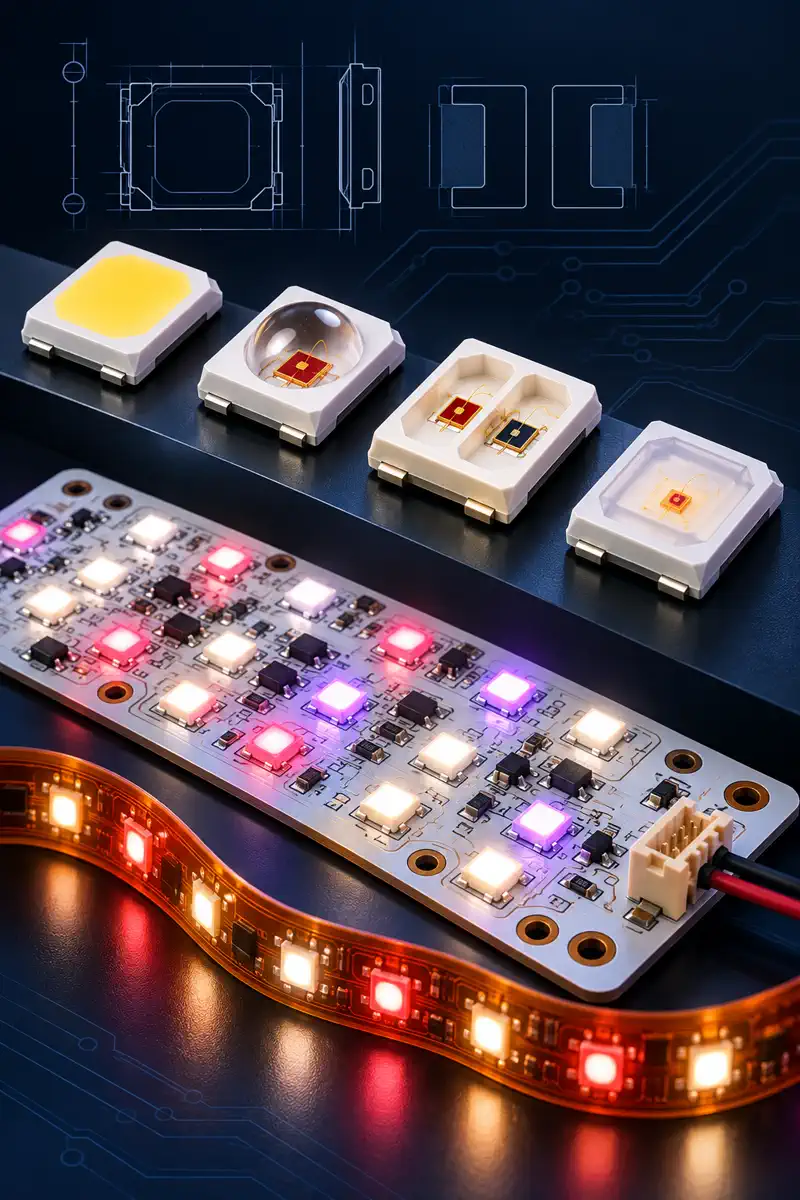
2835 LED Packages for Wavelength-Specific Light Sources
A 2835 package can support very different systems depending on its spectrum, channel structure, driver and board design.

Phototherapy and Beauty Equipment
Red, infrared, blue or multi-wavelength packages can be integrated into equipment light-source boards. Product safety, treatment claims and clinical performance remain subject to validation by the finished-device manufacturer.
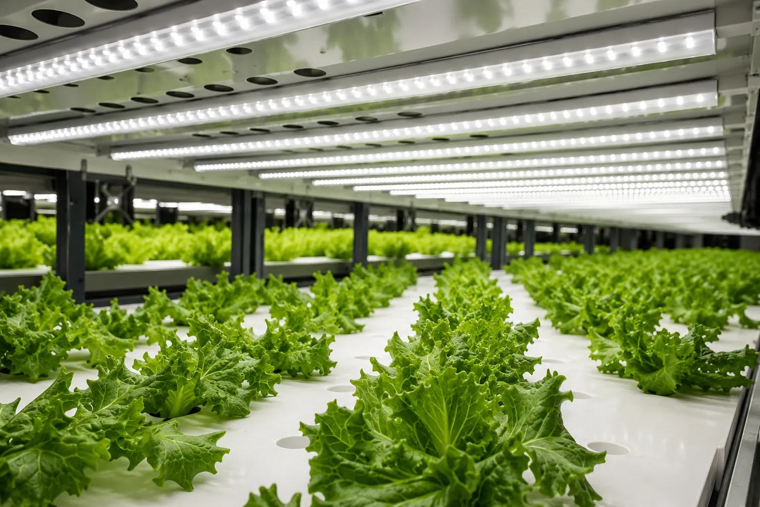
Horticulture Lighting
Red, blue and combined-spectrum packages can support plant-lighting source designs. Select the final spectrum according to the crop, fixture and operating strategy.

UV Curing and Violet Illumination
Violet and UVA options can support curing-related and wavelength-specific illumination designs. Validate material response, optical dose and thermal conditions in the complete system.

Infrared Sensing and Machine Vision
Near-infrared and red-plus-infrared arrangements can support sensing and inspection systems. Match the emitter with the detector, filters and working distance.
Indicators and Specialty Illumination
Visible-color and white configurations can be selected for status indication, equipment lighting and other compact surface-mount assemblies.
RGB and Dynamic Color
Three-channel RGB structures support controllable color output where the driver and control architecture are designed for the selected package.
Review the Exact Part Before Approval
Package design involves more than external size. Confirm the outline, pad layout, polarity, chip arrangement, wavelength or CCT, forward voltage, forward current and optical metric on the exact part document.
Include These Details in Your Request
- Target wavelength, visible color or white-light CCT
- Required channel count or chip combination
- Flat or dome package preference
- Power and current target
- PCB, FPC or driver constraints
- Application and operating conditions
- Estimated order requirement
If an existing configuration does not match the design, submit the required optical and electrical targets for a feasibility review.
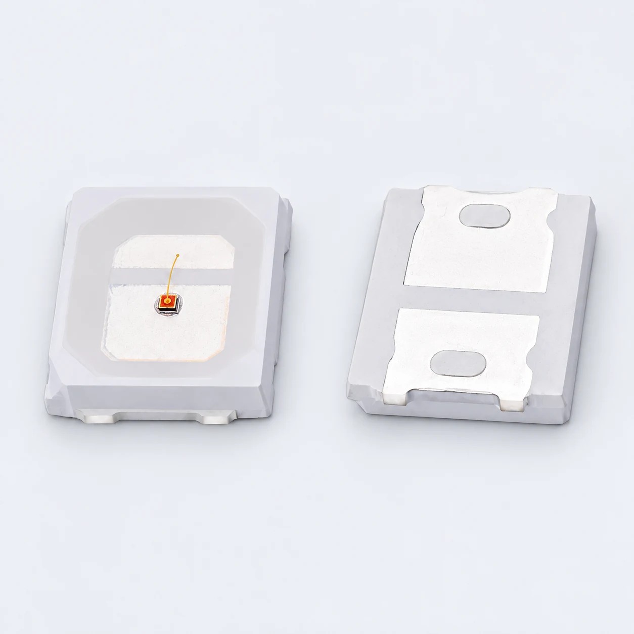
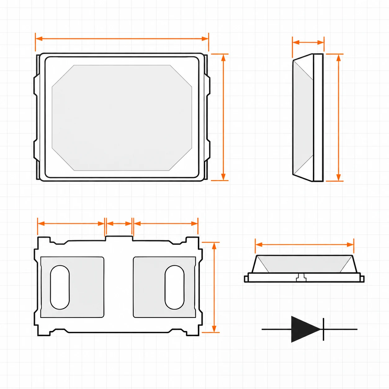
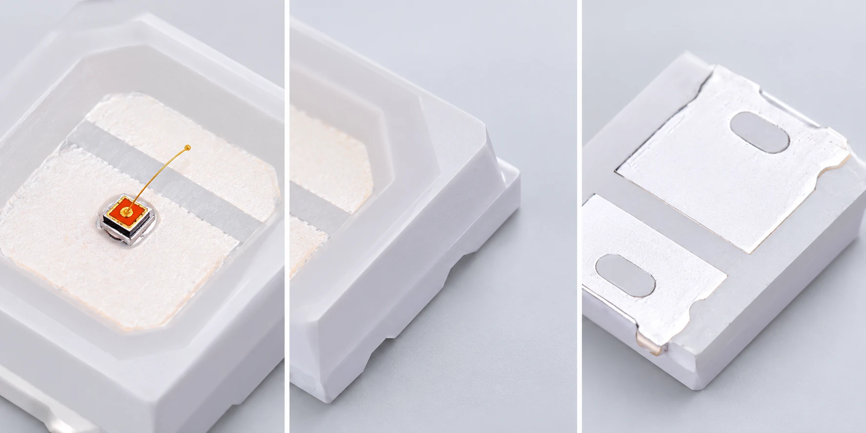
What Does 2835 Mean in an SMD LED?
The number identifies a surface-mount package with nominal outer dimensions of approximately 2.8 × 3.5 mm. It does not define the emitting wavelength, white-light CCT, power, voltage, brightness, beam angle or number of chips.
The same footprint can therefore be used for a visible-color LED, a white LED, a UV emitter, an infrared emitter or a multi-channel package. Treat “2835” as a mechanical starting point and use the exact part number and specification for the remaining decisions.
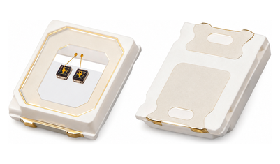
What Is the Typical Brightness of a 2835 SMD LED?
There is no single brightness value for every 2835 LED. Output changes with the emitting color or wavelength, chip configuration, drive current, junction and ambient temperature, and the test method.
| Emitter type | Appropriate output reference |
|---|---|
| Visible white or color LED | Luminous flux or another specified photometric value under stated test conditions |
| UV or infrared LED | Radiant power or another specified radiometric value under stated test conditions |
| Multi-channel LED | Per-channel output and electrical conditions, not one combined generic brightness value |
Compare parts at the same current, temperature and measurement conditions. A lumen value is not an appropriate substitute for the radiant output of an ultraviolet or infrared emitter.
Is a 2835 LED More Efficient Than a 5050 LED?
The package code alone cannot answer this question. A 2835 package is approximately 2.8 × 3.5 mm, while a 5050 package is approximately 5.0 × 5.0 mm, but either format can contain different chips, channel layouts and electrical designs.
Electrical input
Compare voltage, current and actual input power under the same operating point.
Optical output
Use luminous flux for applicable visible emitters and radiant power for UV or infrared devices.
Spectrum or color quality
Match wavelength, CCT and CRI where those values apply.
Thermal conditions
Output and lifetime behavior change with junction and board temperature.
Channel structure
A single-channel 2835 and a multi-channel 5050 do not represent the same design task.
Select between 2835 and 5050 by the complete electrical, optical, thermal and mechanical requirements, not by package size or a general efficiency claim.
What Driver or Power Supply Should Be Used for a 2835 LED?
A discrete 2835 LED package normally requires a constant-current driver or a properly current-limited circuit. Match the forward voltage, rated forward current, number of LEDs in series and parallel, driver headroom, channel control, total load and thermal design.
A power supply selected for a finished LED strip does not automatically suit a bare LED package. The strip may already include resistors, constant-current components or a defined circuit topology that is absent from the individual LED.
How Do I Choose Between Flat, Dome, Single-Chip and Multi-Chip 2835 LEDs?
| Configuration | Useful starting point | Confirm before selection |
|---|---|---|
| Flat package | Broad optical distribution and a lower package profile | Exact viewing angle, package height and board layout |
| Dome package | A more directed optical path may be required | Exact beam angle, lens geometry and working distance |
| Single-chip | One emission channel is required | Wavelength or CCT, electrical conditions and optical output |
| Dual-chip | Two wavelengths or two independently controlled channels are required | Internal connection, channel current and control method |
| RGB or multichannel | Controllable color or several emission channels are required | Channel structure, IC or non-IC direction, driver and color-mixing conditions |
Package form describes the construction direction. The approved part drawing and specification define the actual dimensions, connection and optical behavior.
What Should I Check Before Sourcing 2835 SMD LEDs?
- Confirm that the supplier is quoting the packaged LED rather than a finished strip or an unrelated package size.
- Request the exact package outline, polarity and recommended pad reference.
- Confirm wavelength or CCT, forward voltage, forward current and the applicable optical-output metric.
- Check whether values are typical, maximum, optional or tied to specific test conditions.
- For multi-chip packages, confirm the channel connection and per-channel electrical conditions.
- Review the LED together with the driver, PCB or FPC layout and thermal path.
- Approve the final part by its drawing, specification and sample rather than the 2835 name alone.
The current 2835 range includes visible-color, white and dual-CCT, red and infrared, UV and violet, RGB and horticulture spectrum directions, with package-to-board coordination available when the project requires a complete light-source assembly.
Continue Your Product Search
Explore SMD LED Packages
Review other surface-mount package sizes and light-source directions.
View SMD LED OptionsRed and Infrared 2835 LEDs
Review red, near-infrared and multi-channel package directions.
UV and Violet 2835 LEDs
Review cataloged violet and UVA wavelength directions.
Custom PCB, FPC & PCBA
Coordinate LED package selection with the board, circuit and assembly requirements.
Tell Us the 2835 LED You Need
Share the optical, electrical and mechanical targets for your project. Include the intended application so the package and board conditions can be reviewed together.