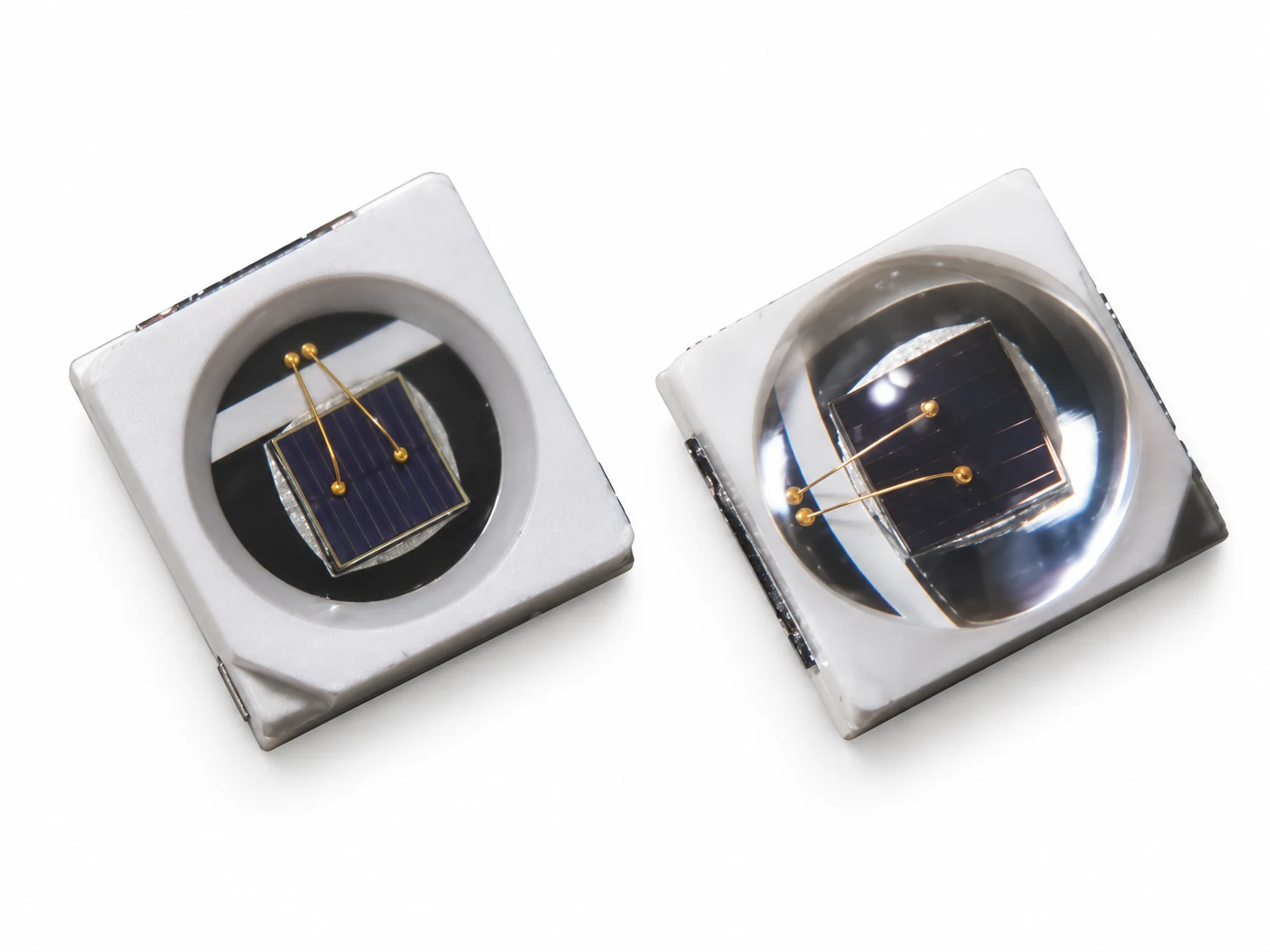
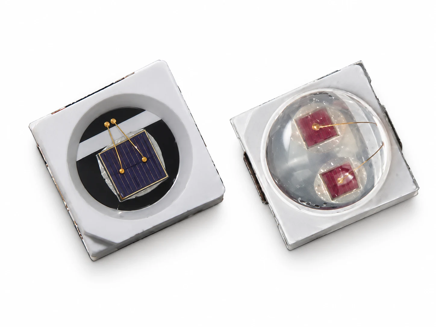
3030 SMD LED Macro View

3030 SMD LED Manufacturer for Custom Light Sources

Choose the 3030 package by its spectrum, optical shape and electrical design—not by package code alone. Leienda develops and produces LED packages in Shenzhen, with single-color and dual-chip 3030 structures and RGB or RGBW configurations for project review. We can also coordinate the selected LED with a PCB, FPC or PCBA light-source assembly.

Explore 3030 Configurations

3030 SMD LED Configurations

The same package designation can cover different emitters, lens profiles and circuit arrangements. Start with the light and control your product needs, then confirm the exact drawing and electrical data for the selected part.

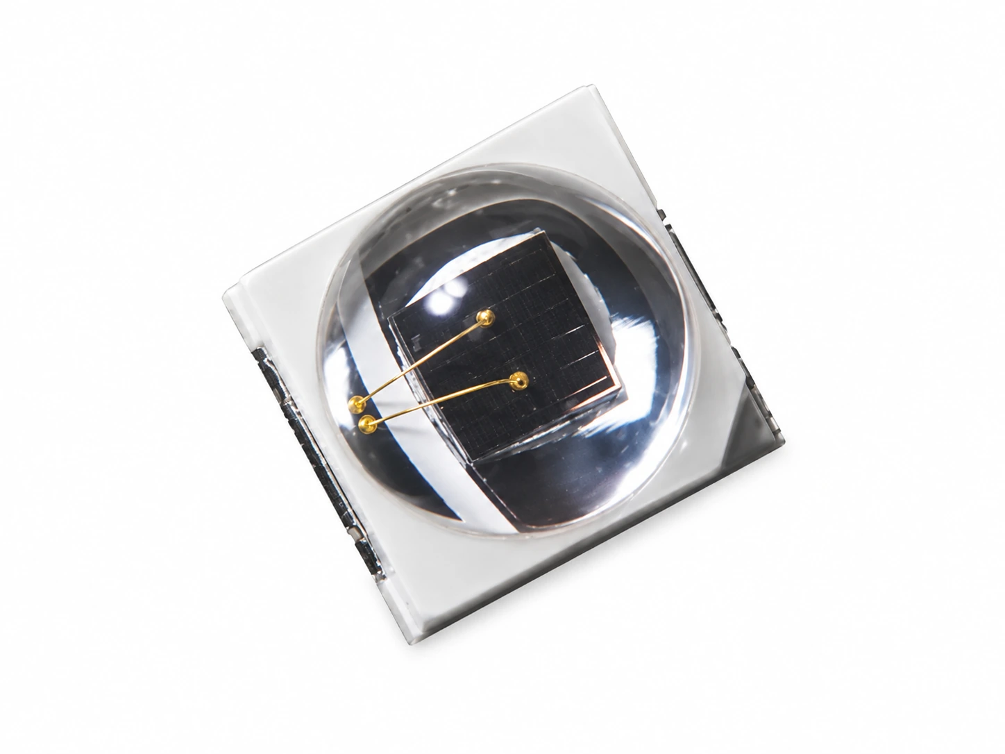
Single-Color 3030 SMD LED device

Single-Color 3030 SMD LEDs

One selected color, wavelength or white-light specification in a flat-top or domed package. Compare wavelength or CCT, beam distribution and assembly height for your board.

Discuss Single-Color 3030 LEDs
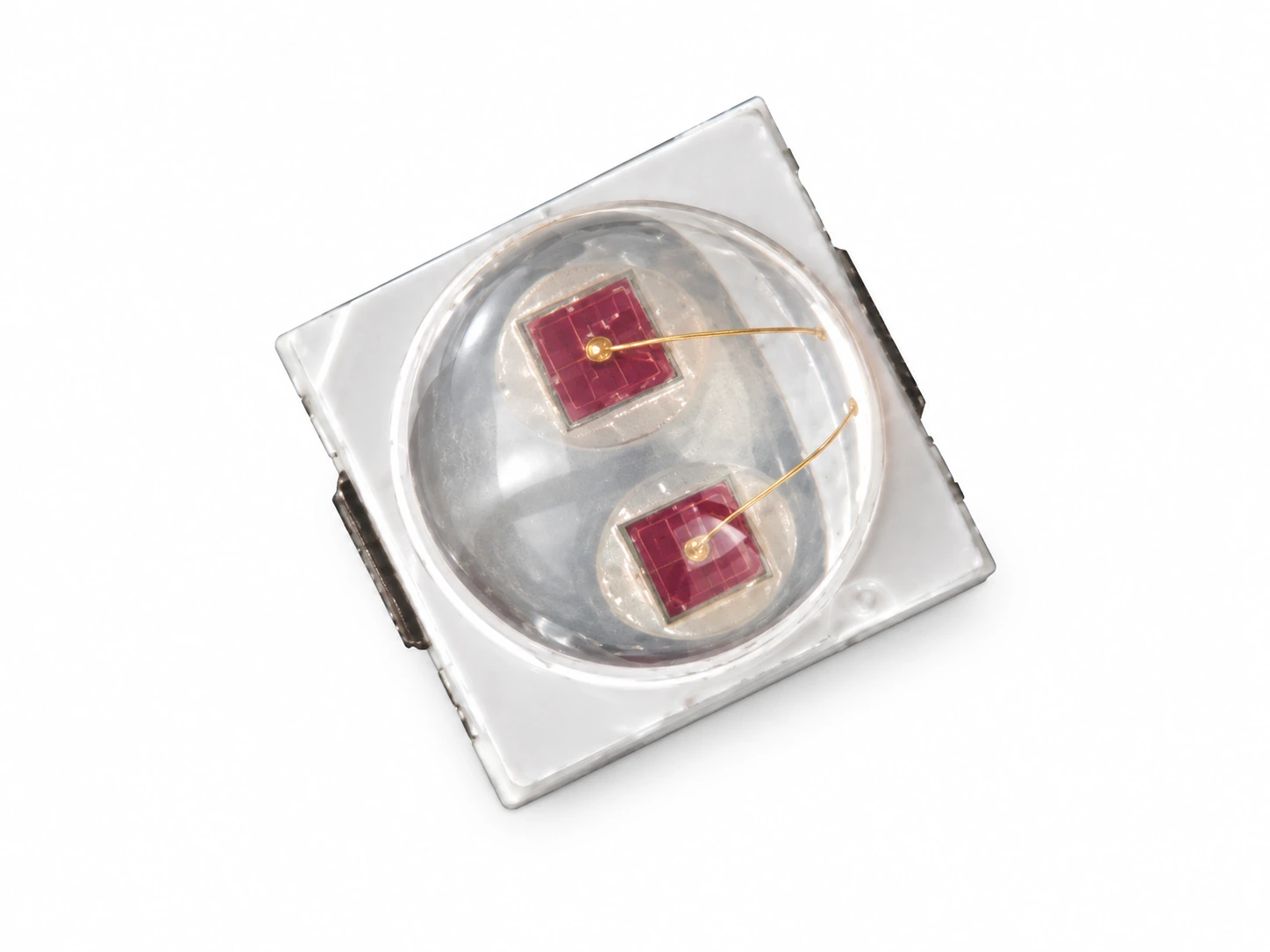
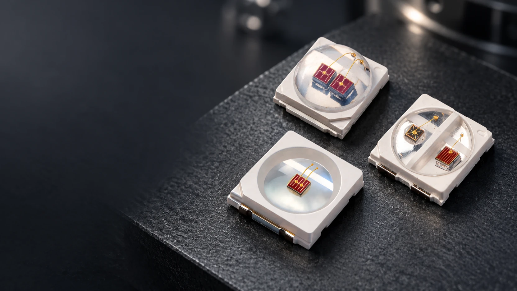
Dual-Chip 3030 SMD LED device showing two emitters

Dual-Chip 3030 SMD LEDs

Two emitting dies in one package support compact same-color or mixed-wavelength designs. Red and near-infrared combinations are useful when both sources must fit within a dense light board; verify the electrical connection and output of each emitter before laying out the circuit.

Discuss Dual-Chip 3030 LEDs
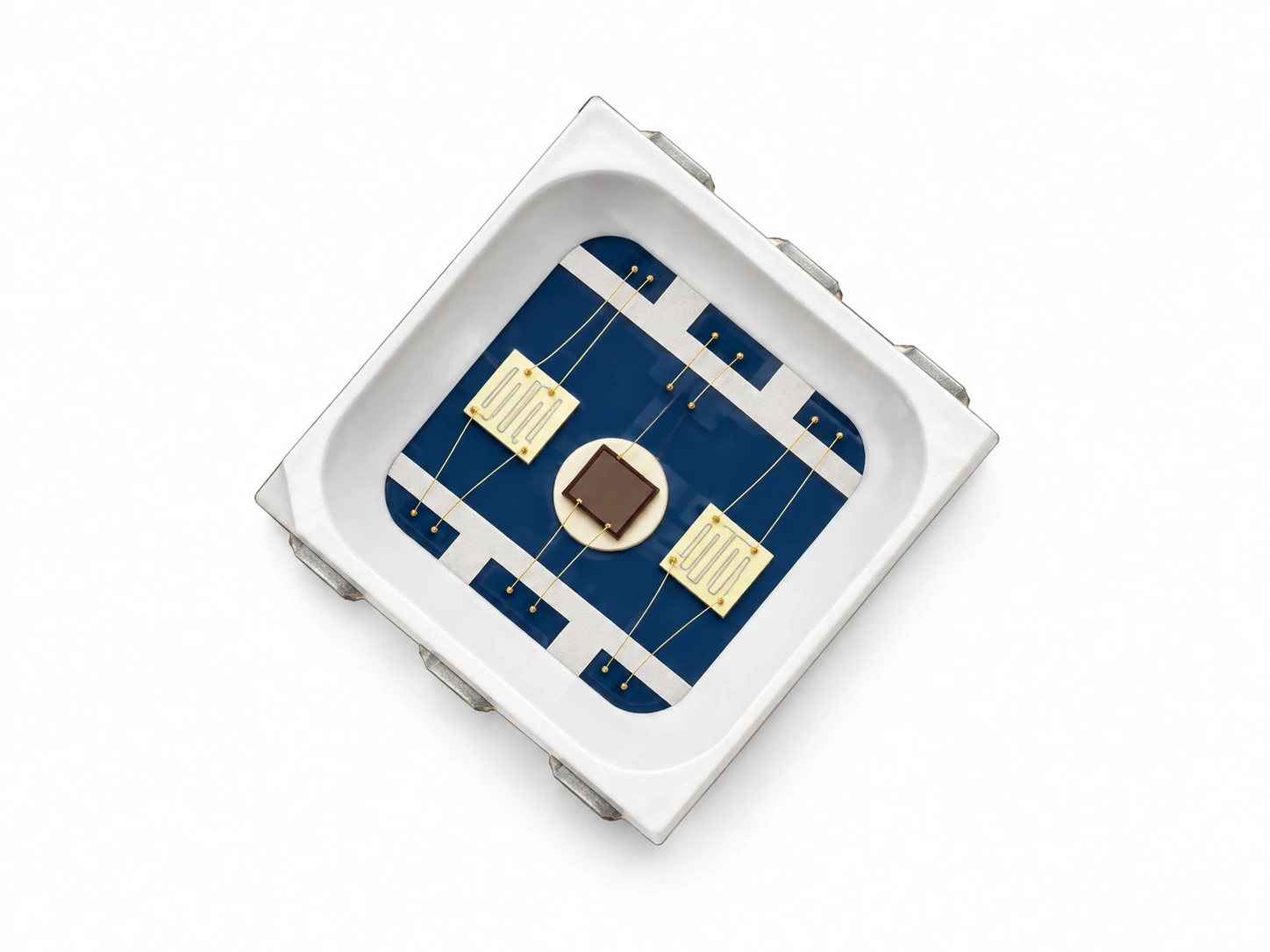
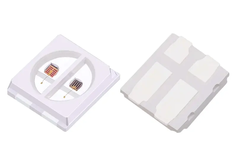
3030 RGB SMD LED device structure

3030 RGB SMD LEDs

Red, green and blue emitters provide color-mixing options in a 3030 format. Conventional multi-channel and IC-integrated constructions call for different pinout and control reviews; select the actual part before fixing the driver design.

Discuss an RGB Configuration
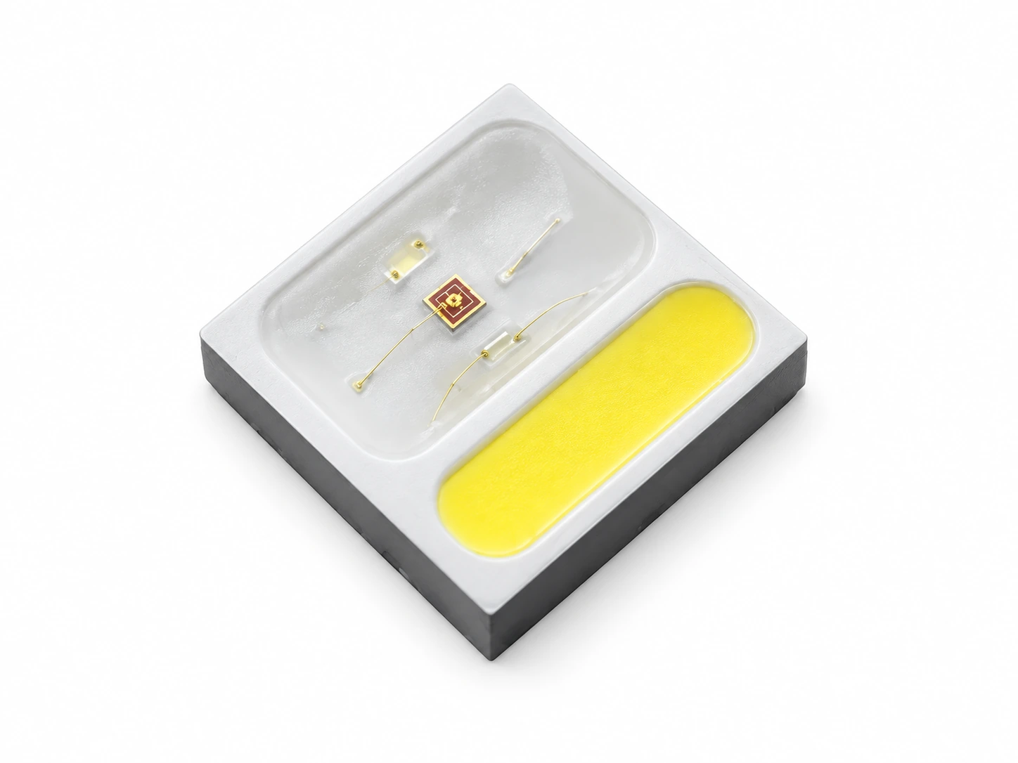
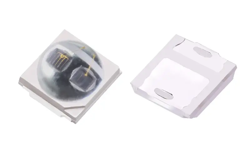
3030 RGBW SMD LED device with four emitters

3030 RGBW SMD LEDs

A dedicated white emitter adds a fourth channel to RGB color mixing. Compare the non-IC 3030 RGBW package with a ceramic 3030 RGBW SMD construction for your white-light target, channel drive, pinout and board-level thermal path.

Discuss an RGBW Configuration

How to Select a 3030 LED

Design decision What changes What to verify
Emission type Single-color, dual-chip, RGB and RGBW designs solve different spectrum and control needs. Target wavelength or CCT, emitter count and the required electrical channels.
Optical shape Flat-top and domed packages distribute light differently. A dome may concentrate more light toward the center, depending on the part. Viewing-angle data and output at the actual working distance.
PCB fit “3030” identifies a package class; it does not guarantee that two suppliers’ body outlines or solder pads are interchangeable. Current mechanical drawing, pad pattern, polarity and component clearance.
Output measure White-light flux and infrared radiant output answer different questions and should not be ranked on one “brightness” scale. Correct unit, test current, temperature and optical measurement conditions.
Thermal and drive design Current, forward voltage and heat flow belong to the selected emitter and board design, not to the package name alone. Part-specific ratings, circuit arrangement, board material and operating temperature.
Comparison of flat and domed 3030 LED profiles

Flat or domed?

Choose a flat-top package when a broad board-level distribution suits the optical design. Review a domed option when the center intensity or working distance matters more. Confirm the beam data for the actual model; the lens shape alone does not establish a fixed viewing angle.

Circuit connection diagram for multi-channel 3030 LED

One wavelength or several channels?

A single-color part keeps one optical target in focus. A dual-chip package places two emitters in a compact footprint, including red and near-infrared design options such as 660 nm and 850 nm. RGB and RGBW add color channels, but the required driver and control interface depend on the chosen circuit. Do not assume that two visible dies are independently controllable without a pinout.

3030 LED solder pad layout details 3030 LED assembled on circuit board

Resolve the Details That Affect Your Board

A package name is not a complete specification.

Selecting by “3030” alone can leave pad dimensions, polarity, current and optical output unresolved until the PCB is already designed. Compare the current drawing and part-specific electrical data before locking the footprint.

Two emitters need two clear sets of data.

For red and near-infrared designs, one combined power figure cannot explain the output of each wavelength. Review the connection scheme, forward voltage, drive current and optical output for each emitter against the intended control method.

The LED and the board must work together.

Lens height, emitter spacing and heat flow affect an assembled light source. Leienda can review the packaged LED alongside PCB, FPC, SMT and PCBA requirements so component selection and board layout are discussed within the same project.

Review a 3030 Board Design

Match the 3030 Configuration to the Equipment

Red and near-infrared light-source assemblies

Red and near-infrared light-source assemblies

Dual-emitter red and near-infrared options can help place two wavelengths on a compact mask, belt or other light board. Specify the optical output of each channel and validate the complete device at its intended operating distance.

Horticulture lighting board

Horticulture lighting

A plant-lighting board may need a particular red, blue or mixed spectrum rather than a generic “grow LED.” Evaluate the target wavelengths, emitter arrangement and fixture-level spectrum together.

White and color lighting assembly

White and color lighting

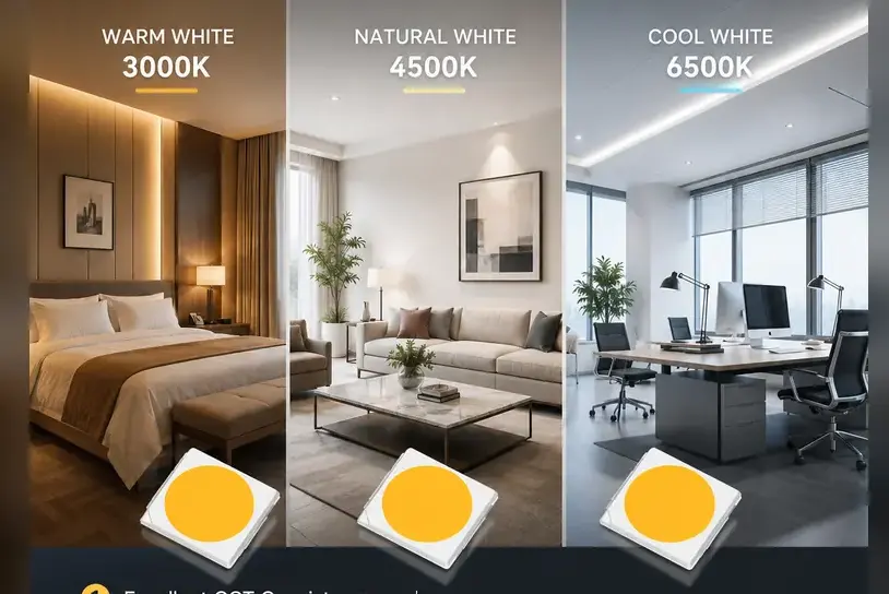
For white-light designs, compare CCT, color quality, flux and thermal conditions at the chosen current. For color-changing products, choose RGB or RGBW based on the required white output and channel-control scheme.

Infrared illumination and sensing

Infrared illumination and sensing

Start with the target wavelength, optical path and detector or camera response. Confirm radiant output under the selected drive condition rather than substituting visible-light lumen figures.

Component Choices With Assembly in Mind

Several structures within the 3030 family

Single-color, dual-chip and multi-channel designs let the selection begin with spectrum and circuit function. Flat and domed formats add another optical choice without changing the core product intent.

A path from packaged LED to assembled light source

The same project can cover LED selection and a PCB, FPC or PCBA light-source assembly. This helps align the emitter, pad pattern, board shape and channel layout before an assembled design is finalized.

Specifications matched to the selected part

Wavelength, forward voltage, current and optical output should be checked against one identified configuration and its test conditions. A family summary is a starting point; the part-specific sheet and sample review guide the final selection.

LED Production and Inspection in Shenzhen

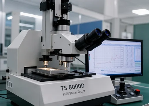
Leienda develops and produces LED lamp beads in Shenzhen and supports their integration into custom light-source boards. Its workflow includes incoming-material and finished-product inspection. For a 3030 project, the relevant optical, electrical and reliability checks should be defined against the selected part and its application requirements.

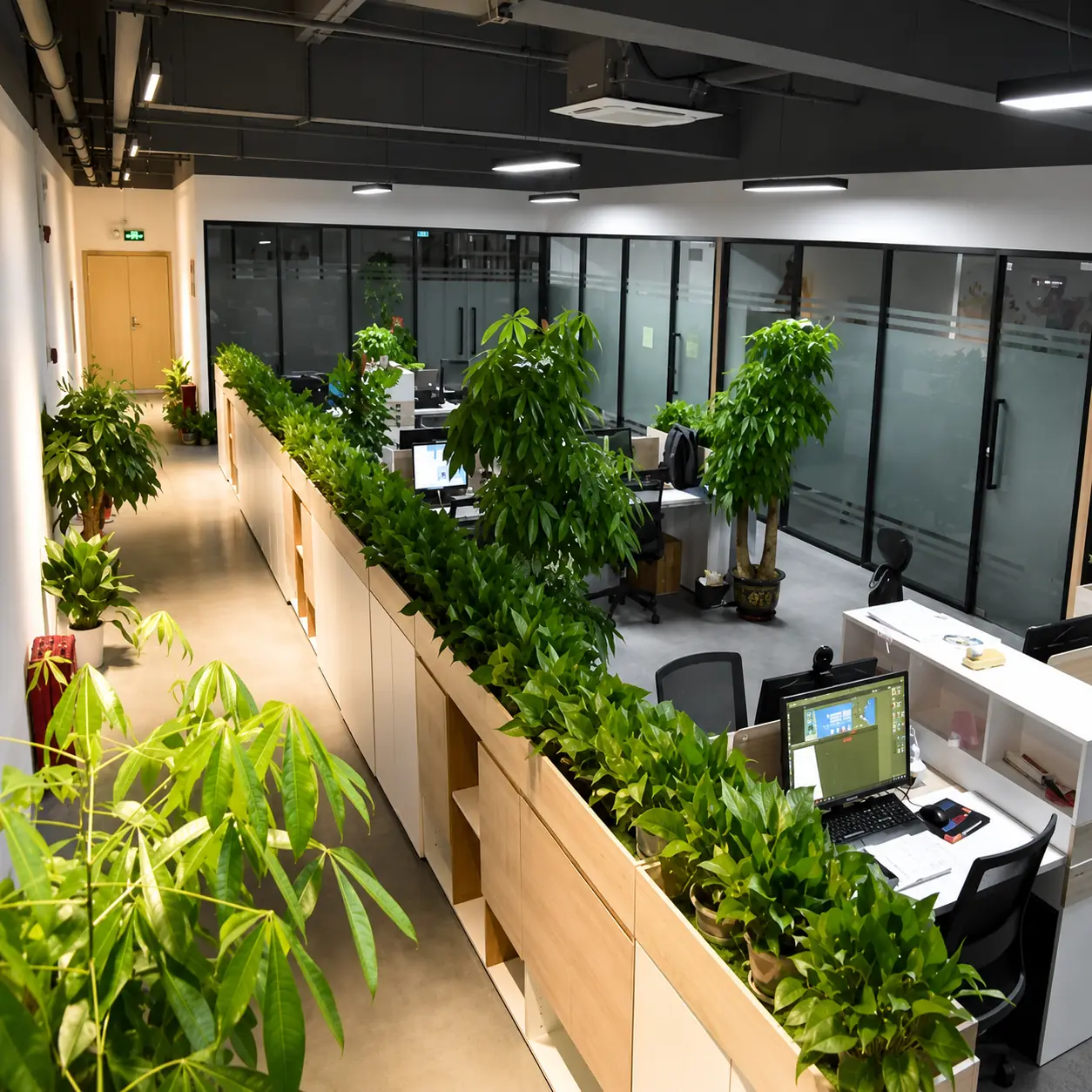
LED packaging production area
Optical measurement equipment

What does “3030” tell me?

It identifies a package size class, not a universal electrical or optical rating. Two 3030 LEDs can differ in emitter count, lens profile, pad pattern, forward voltage and output. Begin with the intended light and circuit function, then verify the chosen model’s drawing and test data before treating it as a replacement part.

What luminous efficacy should I expect?

There is no responsible single lm/W value for every 3030 LED. For a white-light part, divide measured luminous flux by electrical input power under stated current and temperature conditions, then compare like CCT and color-quality bins. A near-infrared part is evaluated with radiant output, usually in milliwatts, so a visible-light lm/W comparison does not describe its purpose. Request the figures for the actual model and operating point.

What belongs in a 3030 datasheet?

A useful part-specific sheet identifies the mechanical outline and pads, polarity or pinout, forward voltage and current, optical output with units and test conditions, wavelength or CCT bins, viewing angle, thermal limits and applicable soldering guidance. Multi-emitter parts need channel-level data. Leienda’s single-color, dual-chip, RGB and RGBW configurations should be reviewed by the corresponding part details rather than one family-wide number.

How does 3030 compare with 5050?

The package codes indicate different nominal footprint classes, but neither code sets power output by itself. A larger package may offer different emitter and circuit layouts; an individual device’s usable output still depends on its die design, drive current, optics and thermal path. Leienda’s 3030 and 5050 ranges should be compared using identified models when board space, channel count or optical output drives the decision.

How should I drive several 3030 LEDs in series?

Use a driver suited to the target current, and check that its voltage range covers the sum of the selected LEDs’ forward voltages with appropriate design margin. LEDs in one series string must suit the same current. For dual-emitter, RGB or RGBW designs, first inspect the actual pinout and channel connections; separate channels may need separate current control. Confirm the board’s thermal conditions at the intended operating point.

Explore Related Light-Source Options

Discuss Your 3030 LED Design

A useful review starts with the light your equipment needs and the space available for it. Share the target wavelength or CCT, board drawing, drive conditions and intended quantity if known. We can use those details to discuss the appropriate 3030 structure and the specification required for evaluation.

4/F, No. 8 Guanghui Road, Longteng Community, Shiyan Street, Bao'an District, Shenzhen, Guangdong, China

Supported formats: PDF, JPG, PNG, STEP, IGES, STL, DWG (Max 20MB)