COB LED Light Source Manufacturer for Custom Spectrum Projects
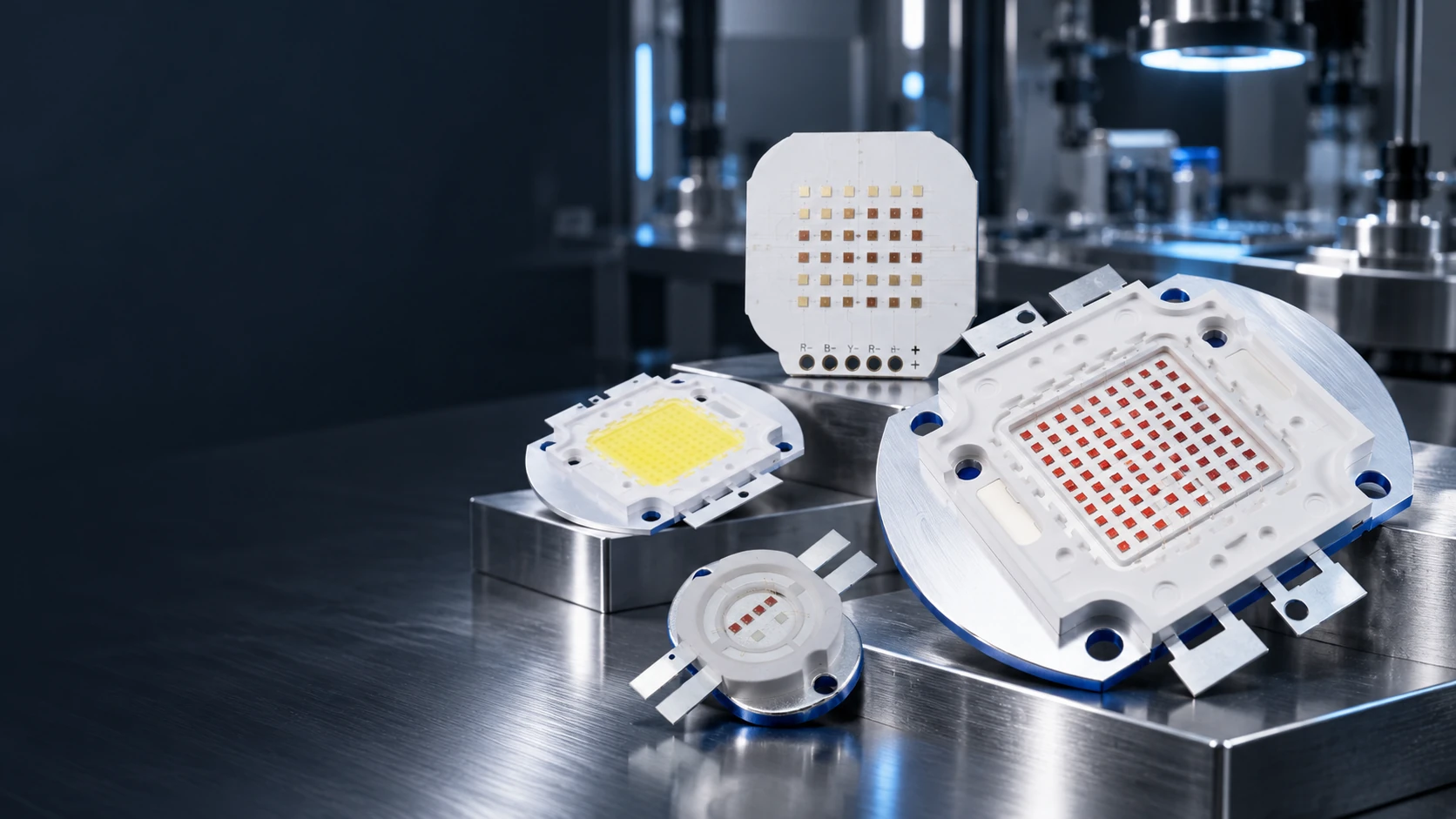
Bring multiple LED dies together on one substrate for a compact, integrated light source. LEIENDA supplies white, single-wavelength and multi-wavelength COB directions, and discusses substrate, channel and module configurations around the intended equipment.
Explore COB LED Light Source Options
Start with the light you need, then check the emitting area, electrical channels, substrate and thermal path. The same COB construction name does not establish one universal power, voltage or optical output.
White COB LED Light Sources
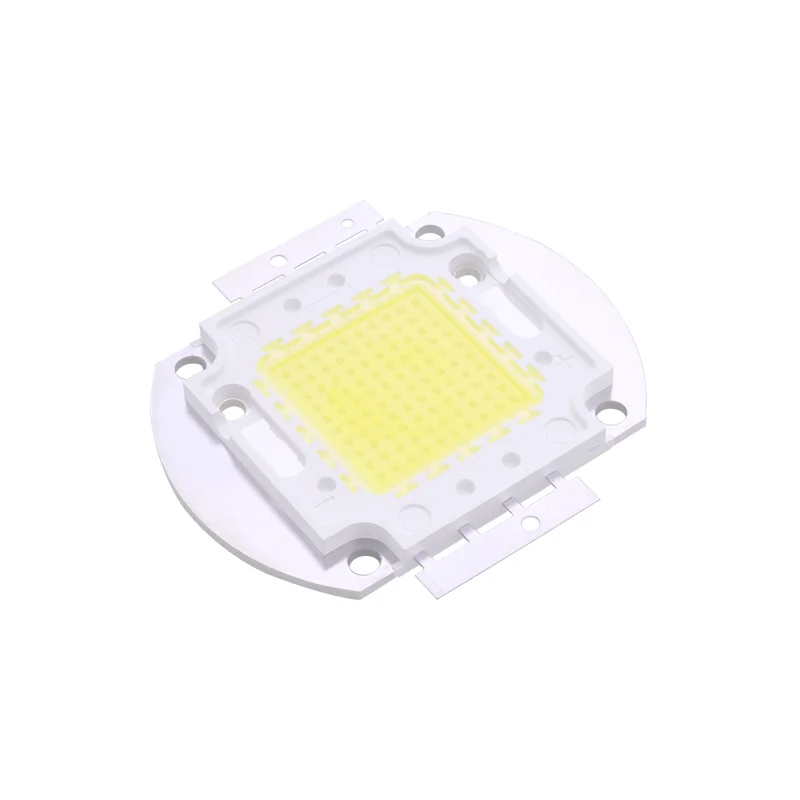
White and warm-white COB examples provide a concentrated emitting area for lighting and equipment designs. Compare color temperature, color-rendering requirement, light-emitting surface, output at a stated drive condition and the intended optic before selecting a source.
Discuss White COB Options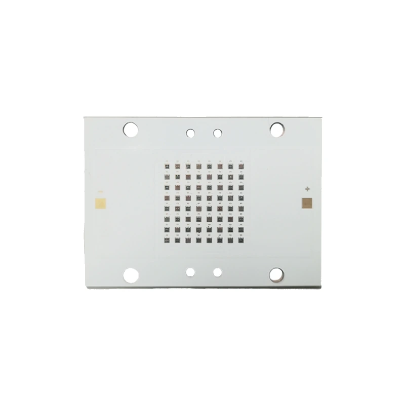
Single-Wavelength COB LED Light Sources
Red and infrared COB examples serve projects defined by a target emission band rather than white-light color temperature. Select the actual part by peak wavelength, optical output, drive condition and substrate format; a product photo alone cannot establish those values.
Discuss Red or Infrared COB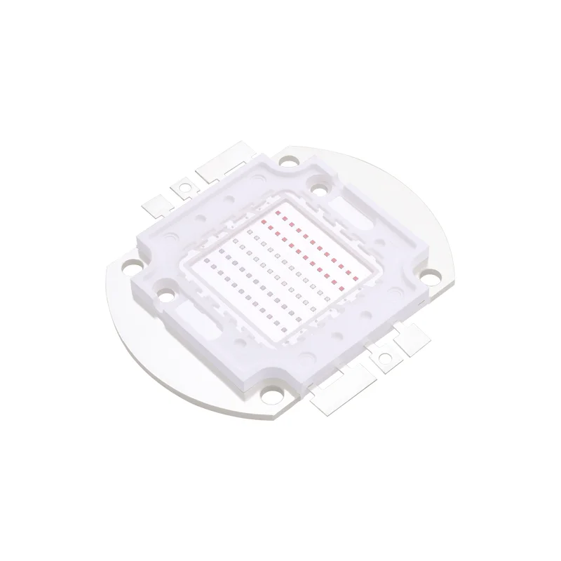
Multi-Wavelength COB LED Light Sources
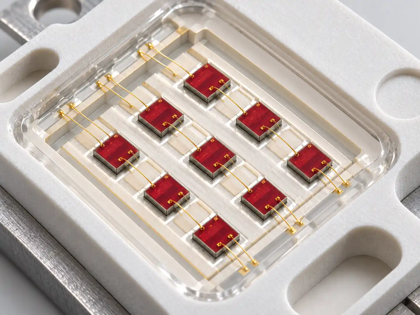
Red/blue, red/infrared, RGB and RGBIR examples bring different emitters into one integrated source. Compare the required spectral combination, channel arrangement, electrical interface and mixing result in the final optical system.
Discuss Multi-Wavelength COB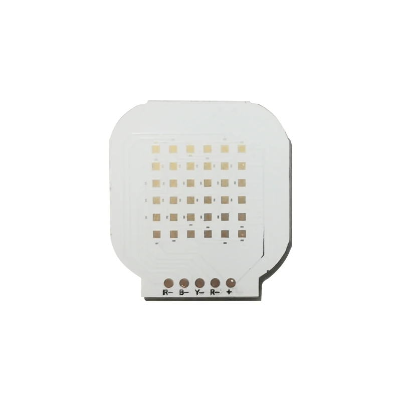 Multi-channel COB source
Custom COB LED Modules
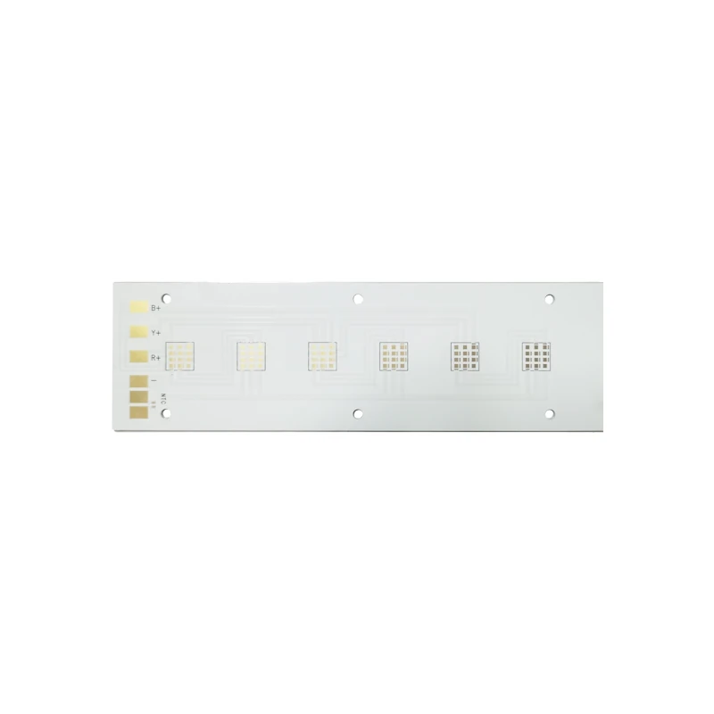
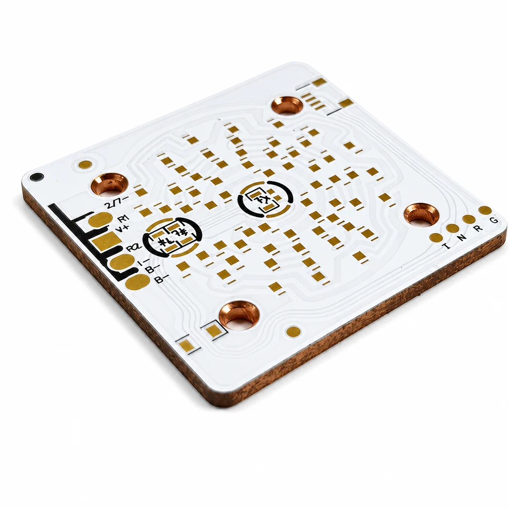
For equipment that needs more than a listed light source, discuss the target spectrum, emitting area, substrate, channel layout, mounting and board interface as one project. The pictured multi-channel copper-substrate COB is a configuration example; the final module design and specifications depend on the approved project requirements.
Discuss a Custom ModuleCOB or Discrete SMD LEDs? Match the Source to the Layout
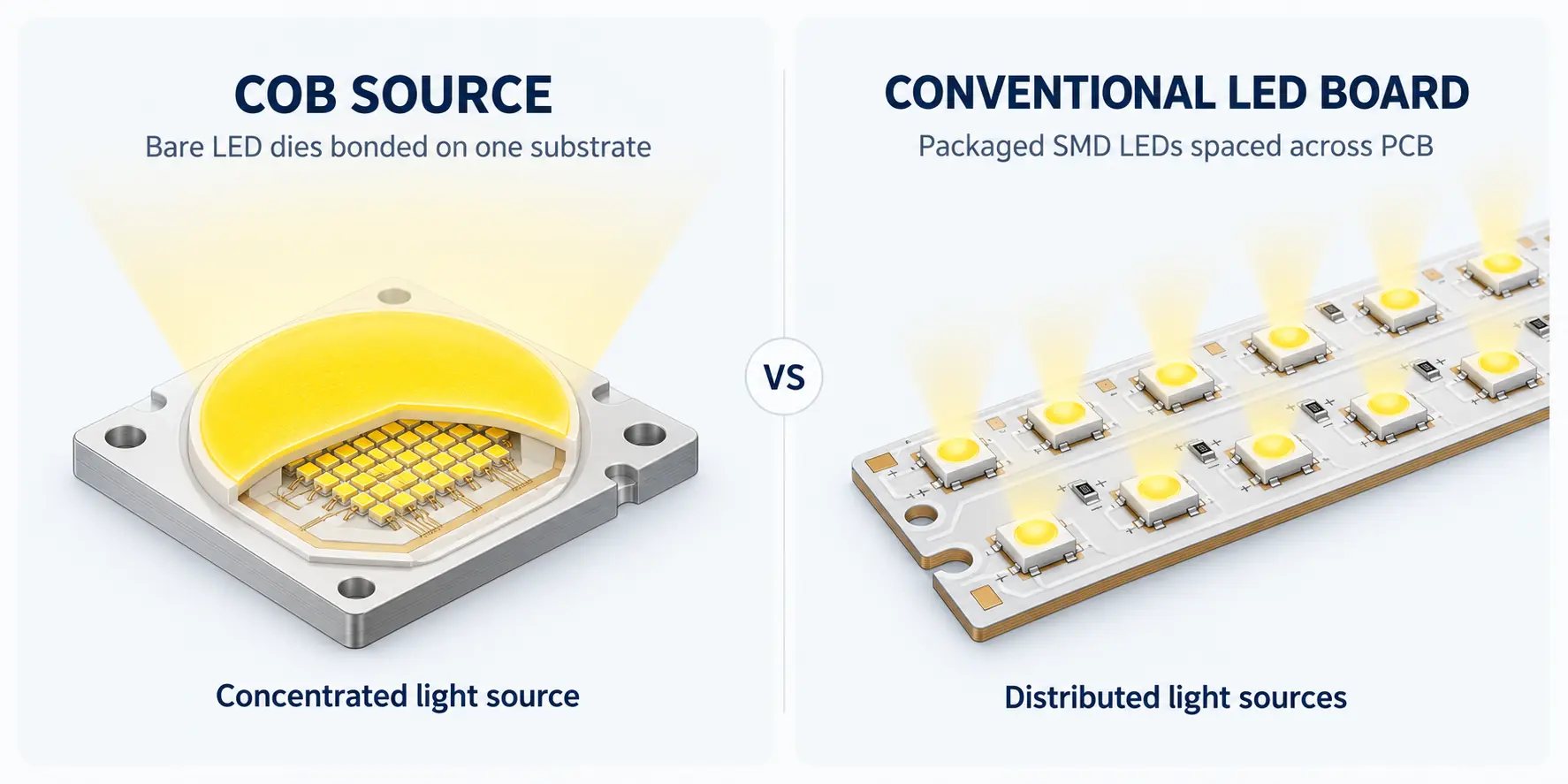
COB describes how multiple LED dies are integrated on a shared substrate. SMD LEDs are individual packaged devices placed across a board. The right choice depends on the size and distribution of the emitting area, optical control, electrical channels and heat path—not on a claim that one format is always better.
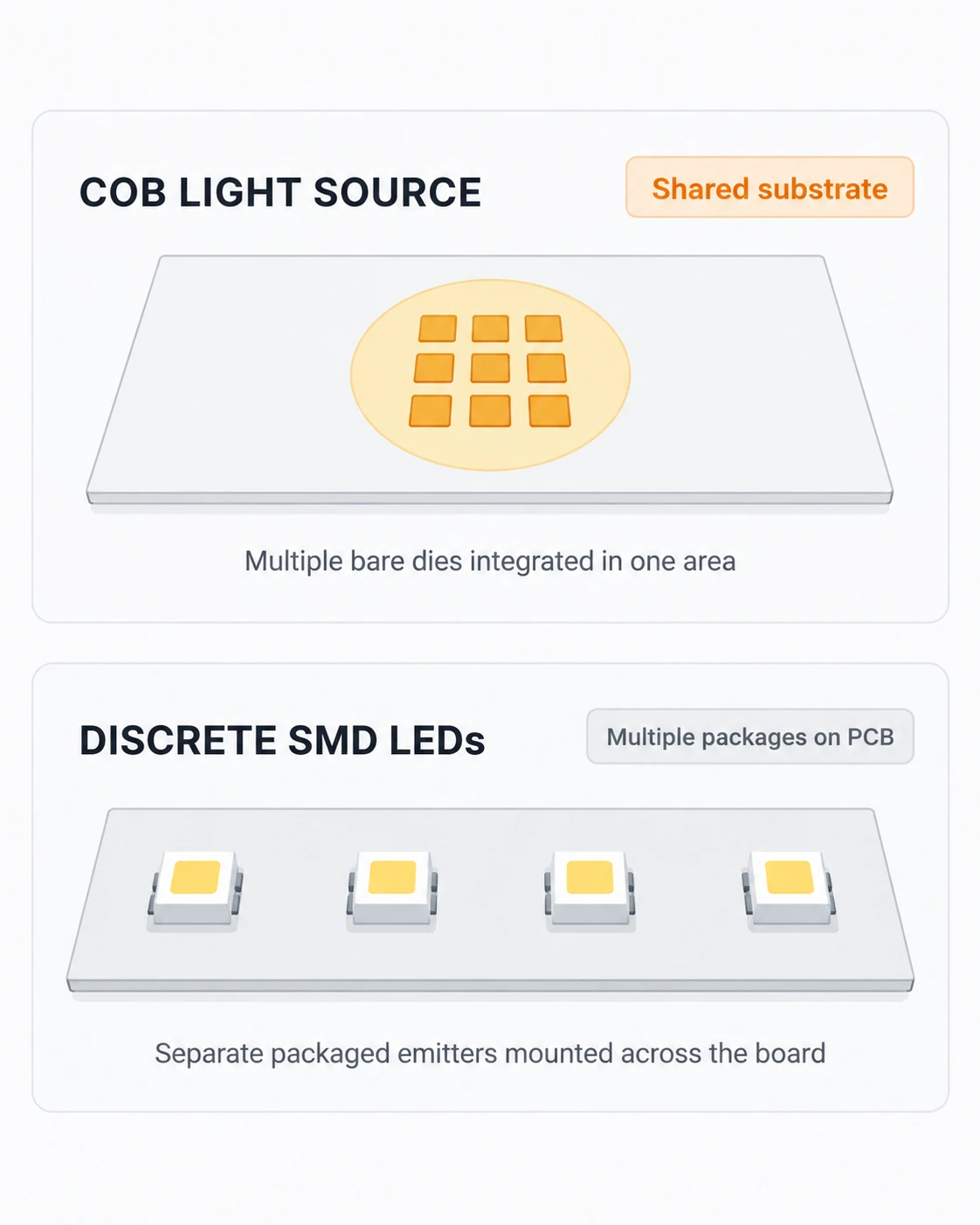
| Design question | COB light source | Discrete SMD LEDs |
|---|---|---|
| Where should light originate? | From one integrated emitting area | From multiple positions across a PCB or FPC |
| What controls the layout? | The selected COB footprint, emitting surface and optic | Package spacing, board shape and individual placement |
| How should channels be planned? | Confirm the selected COB’s terminal and channel arrangement | Plan package count, traces and channel grouping on the board |
| What must be checked thermally? | Substrate-to-heat-sink path and operating conditions | Package-to-board path and the complete board assembly |
Uniformity, beam shape and working temperature must be validated in the finished optical and thermal design.
Resolve the Light Source Before the Equipment Design Is Locked
Check the spectrum, thermal path, electrical channels and module interface together before finalizing the equipment design.
The spectrum fits the idea but not the actual source
A red, infrared or mixed-color label is only a starting point. A mismatch in peak wavelength, channel balance or measurement conditions can change the result of the finished equipment. LEIENDA’s single- and multi-wavelength COB examples give the project a concrete configuration to review against the target spectrum.
The COB fits the opening but not the thermal path
A compact emitting area still needs a suitable path into the mounting structure and heat sink. Review substrate format, contact area, operating current and the planned case or heat-sink temperature before approving the mechanical design.
One source becomes several uncontrolled electrical channels
Red/blue, red/infrared and RGBIR designs may require different channel control from a white or single-band source. Confirm the selected unit’s terminal layout and drive conditions before committing to the driver and PCB interface.
A component choice does not finish the module
When the equipment needs a board, connector or shaped assembly, source selection and module design should be reviewed together. LEIENDA can discuss COB configuration alongside PCB/FPC and PCBA light-source integration requirements.
Build the COB Specification Around the Complete System
Compare candidate sources under stated test conditions. Power alone does not tell you whether the light source will fit the optic, driver, enclosure or heat sink.
| Selection field | What to establish | Why it matters |
|---|---|---|
| Spectrum or white-light quality | Peak wavelength and spectral distribution, or CCT and CRI for white light | Defines whether the output suits the intended task |
| Optical output | Luminous or radiant output at a stated current and temperature | Makes candidate sources comparable |
| Emitting surface and outer dimensions | Light-emitting area, board dimensions, mounting points and optic clearance | Determines the optical and mechanical fit |
| Electrical configuration | Forward-voltage range, operating current, polarity and channel connections | Guides driver and control design |
| Substrate and heat path | Selected substrate, mounting surface, thermal interface and heat-sink conditions | Supports system-level temperature review |
| Verification documents | Current model specification, drawing and agreed measurement conditions | Keeps sample evaluation and purchasing aligned |
Copper and Aluminum Substrate Directions
Company product examples include both copper-substrate and aluminum-substrate COB constructions. Select the substrate with the required size, electrical layout, mounting method and thermal design in view. Compare the actual model and assembly conditions rather than assuming one material guarantees a result.
Review a COB Configuration
Copper-Substrate COB Construction
Aluminum-Substrate COB Construction
Match the COB Source to the Equipment
White-Light Equipment and Luminaires
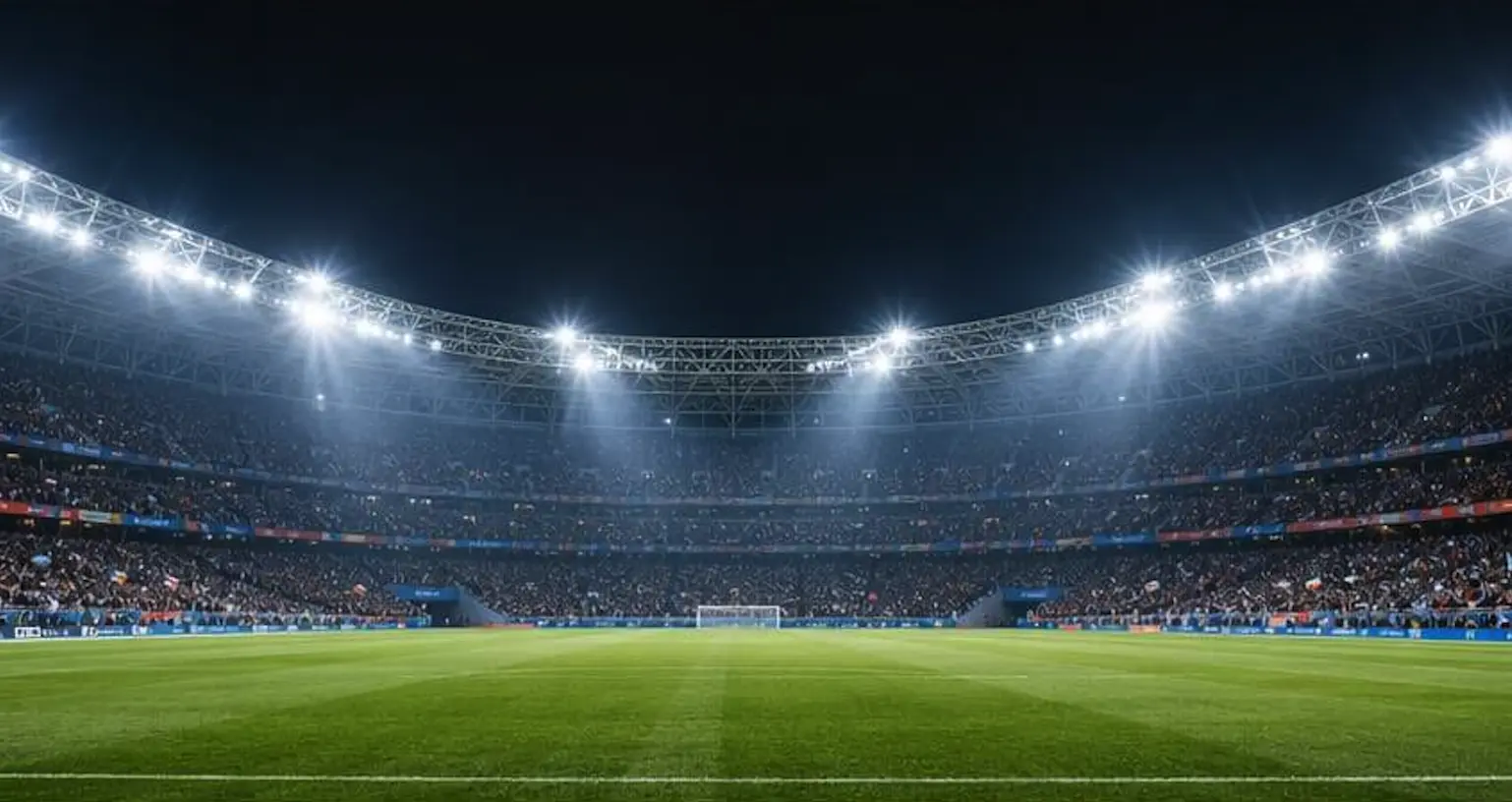
Start with the required beam, color temperature and color rendering, then match the COB emitting surface to the reflector or lens. Confirm driver current and the heat-sink design before assessing the complete luminaire.
Red and Infrared Equipment
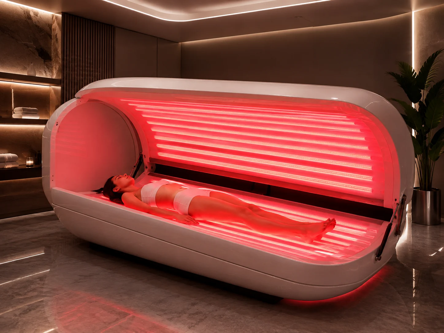
For beauty, wellness or other wavelength-defined equipment, compare the actual red or infrared emission band, radiant output, treatment-area geometry and thermal limits. Any device-level effect or regulatory claim requires validation of the finished equipment.
Horticultural Light Sources
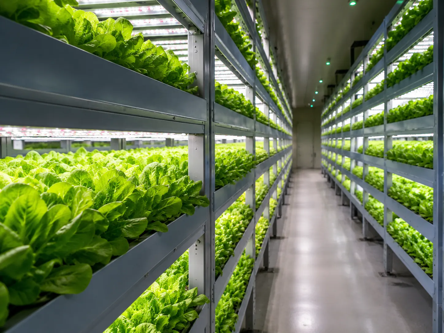
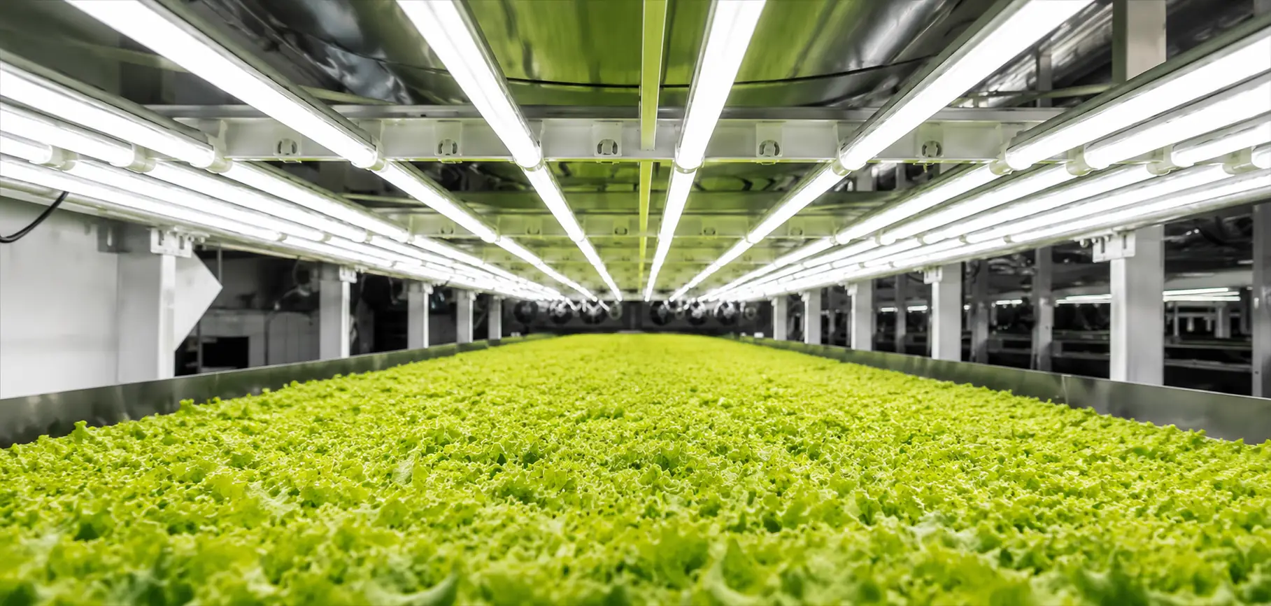
Red/blue and other mixed-spectrum COB directions can be evaluated for plant-lighting equipment. Define the target spectrum and photon output at the intended operating point, then test distribution, distance and temperature in the finished fixture. A COB photo alone cannot establish plant-growth performance.
For work lights or outdoor luminaires, the COB is one component of the finished product. Optics, enclosure protection, electrical safety and heat management must be established for the complete design.
A COB Source That Can Be Discussed as Part of the Assembly
-
More than one spectral starting point — White, red, infrared and mixed-emitter COB examples let the discussion begin with the required light rather than an arbitrary package name.
-
Substrate and channel choices — Copper- and aluminum-substrate examples, plus multi-channel layouts, allow mechanical, thermal and electrical questions to be considered together.
-
A route from source to module — When the equipment requires a board or interface beyond the COB itself, LEIENDA can discuss the light source with PCB/FPC and PCBA integration requirements.
-
Specifications for project review — Product drawings, selected operating conditions and sample measurements provide a clearer basis for comparing a proposed source with the finished equipment.
COB LED Selection Guide
What are the practical advantages of a COB LED source?
Integrating several LED dies on one substrate can create a concentrated emitting area and reduce the number of separate emitters that an optical design must position. It can simplify a suitable source layout, but the finished beam, color mixing and temperature still depend on the chosen COB, optic, driver and heat sink. LEIENDA’s white and multi-wavelength examples illustrate why those choices must be reviewed together.
How is a COB source different from a conventional LED board?
A COB integrates bare LED dies at the light-source level. A board built from SMD LEDs places already packaged devices at positions chosen for the PCB or FPC. Choose the COB route when a concentrated source suits the optic and mounting design; choose distributed packages when the equipment needs light across a shaped or flexible area.
What should be checked before installing a COB in a work light or fixture?
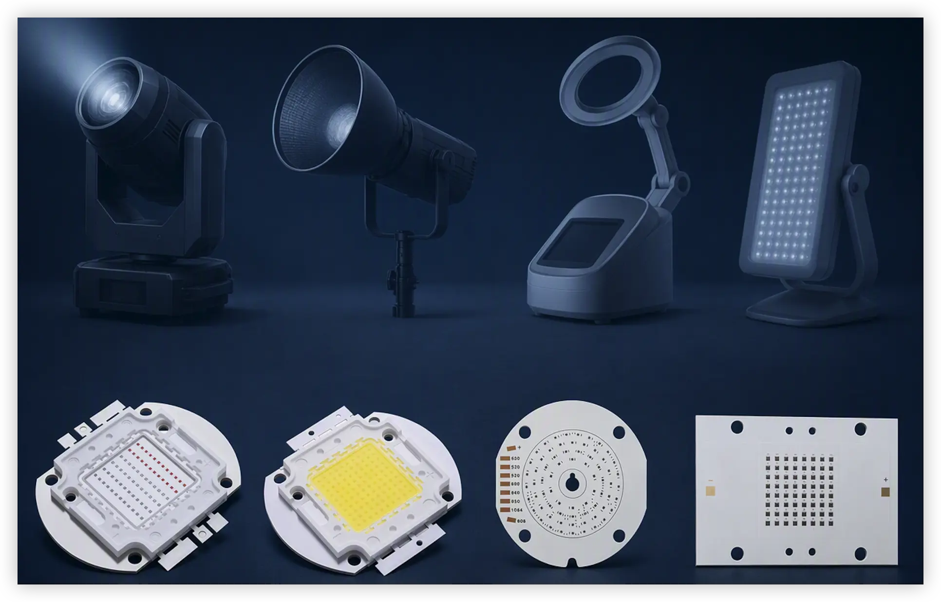
First identify the exact COB’s electrical ratings, polarity, emitting area and mounting drawing. Match the driver to its operating-current and voltage requirements, design a suitable thermal contact and heat sink, then verify the optic and temperature in the assembled fixture. A COB light source is not a complete plug-in fixture, and connection details must follow the selected model’s documentation.
How should a COB source be selected for plant lighting?
Start with the crop and fixture’s target spectrum and photon-output requirements. Compare a red/blue or other mixed-spectrum source at the intended operating point, then evaluate distribution over the growing area and the fixture’s thermal design. LEIENDA’s red/blue COB examples offer a source direction for that evaluation; plant-growth results require testing of the complete lighting system.
Can a COB LED be used in an outdoor luminaire?
It can be considered as a component of an outdoor design, but the bare COB image does not establish an IP rating. The finished luminaire needs a suitable enclosure, sealing, corrosion strategy, electrical protection and thermal design for its actual environment. Validate the complete assembly before specifying it for outdoor use.
What should be verified when sourcing a high-power COB?
Confirm whether the offer is a finished COB light source, a board-level module or an unencapsulated LED die. For the selected item, compare the current specification, drawing, optical data with test conditions, electrical channels, thermal requirements and sample acceptance criteria. Discuss which parts of the source or module can be configured before treating a pictured example as a production specification.
Quality Review from Component to Light Source
LEIENDA develops and produces LED components in Shenzhen and supports COB light-source discussions with product construction information, drawings and optical or electrical review. Incoming-material and finished-product inspection are part of the company’s quality workflow. For a specific COB project, agree on the model, operating conditions, measurements and acceptance criteria before approving the source for the equipment.
Discuss Testing and Documentation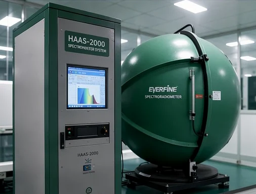
Continue Your LED Source Review
Discuss Your COB LED Configuration
Tell us which light-source direction fits your project and share the optical, electrical and mechanical conditions already defined. A drawing or reference specification can help the discussion focus on the right COB construction, substrate and module interface.