Ceramic High Power LED Manufacturer for Custom Light Sources
Leienda develops and produces ceramic LED packages for projects that need a defined footprint, spectrum and drive configuration. Explore 3535 and 5050 product options, or discuss a 6868 configuration for a larger package layout. Start with the package and optical requirement, then review the exact electrical and thermal conditions for the selected part.
Choose a Ceramic Package for Your Design
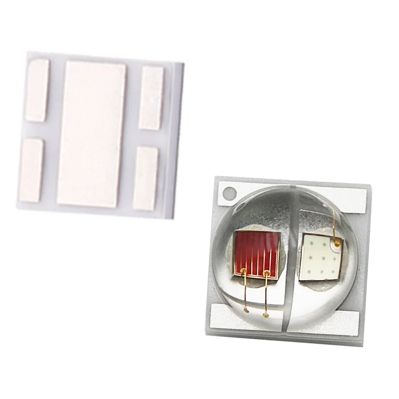
3535 Ceramic High Power LED
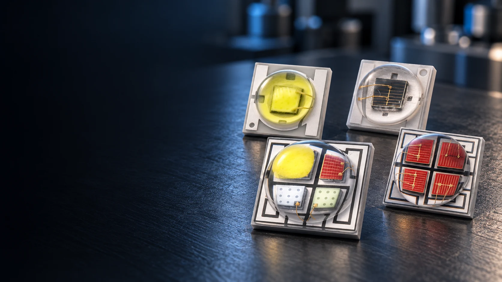
A compact package route with documented white, infrared, red plus infrared, RGB and RGBW examples. Consider 3535 when the board layout and optical system call for a smaller emitting component. The wavelength, channel arrangement and operating conditions must be matched to the exact part.
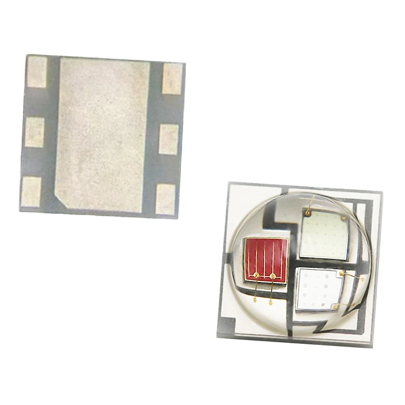
5050 Ceramic High Power LED
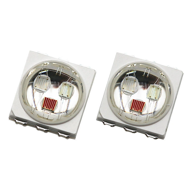
Our ceramic 5050 product images include RGB and RGBW configurations. Its larger footprint gives a different starting point for multi-channel layouts and optical integration. Check the pin arrangement, channel drive conditions and heat path before selecting a part for your board.
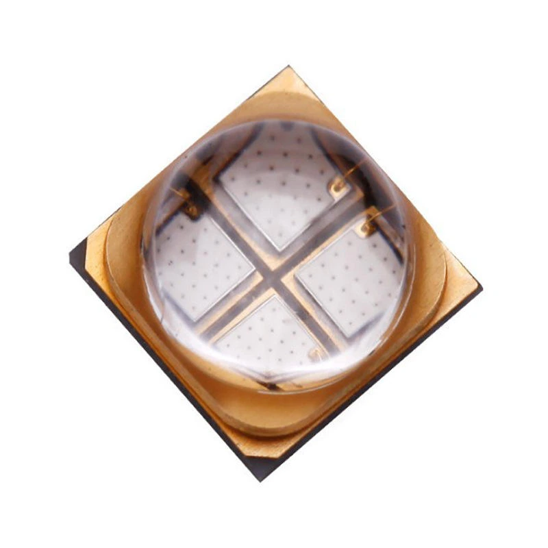
6868 Ceramic High Power LED
For designs that allow a larger package footprint, the 6868 format is a configuration route to review. Confirm the selected construction, drawing, channel arrangement and operating data before fixing the PCB or optical design.
Compare the Package, Not Just the Wattage
The package number identifies a size family; it does not establish the LED’s voltage, current, output or automotive qualification. Compare parts using the same operating conditions and a drawing for the exact construction.
| Selection point | 3535 | 5050 | 6868 |
|---|---|---|---|
| Product evidence | White, infrared and multi-color examples | RGB and RGBW product examples | Package family recorded for configuration review |
| Useful starting point | A compact emitting component | A larger layout for multi-channel designs | A larger package footprint to evaluate |
| Check before design-in | Pad drawing, wavelength and drive conditions | Pin map, channel current and thermal path | Exact part drawing and model-level operating data |
Spectrum and output
For white LEDs, compare color temperature and luminous output under stated test conditions. For red, infrared or other narrow-band emitters, confirm the peak wavelength and the appropriate optical-output unit. Lumens and radiant power in milliwatts answer different questions and should not be compared as if they were interchangeable.
Driver and channels
Choose the driver from the exact part’s forward-voltage and current data. RGB, RGBW and mixed-wavelength packages require the channel arrangement and pin definition to be checked individually. A package footprint alone cannot tell you how its dies are connected.
Heat path and optics
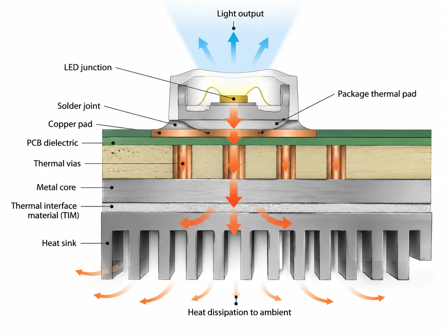
Review the path from the LED junction through the package and solder connection to the board and heat sink. The final operating temperature also depends on the PCB, thermal interface, ambient conditions and drive profile. Check the emitting area, lens form and viewing angle against the equipment’s optics before judging application fit.
Resolve the Decisions That Affect Your Light Source
A familiar package name can hide a different circuit
Two LEDs described as “5050” may have different die counts or channel connections. Selecting by outline alone can lead to a mismatched driver or PCB. Leienda’s ceramic RGB and RGBW examples give you a starting point for discussing the required channel layout; the selected part’s pin definition remains the design reference.
Higher drive demands a complete heat path
A ceramic package is one part of the thermal design. Board material, pad layout, mounting and airflow still affect the operating result. Review the package together with the board and equipment structure so the chosen current is assessed in the intended assembly.
Optical output needs comparable test conditions
A wattage label does not tell you the emitted spectrum or usable light at the target distance. Define the wavelength or white-light requirement, then compare model data at stated current and temperature conditions. This is especially important when evaluating visible light alongside infrared output.
From Ceramic Emitter Selection to a Light Source Assembly
Multiple optical routes
Leienda’s ceramic product materials cover white, single-color, infrared, red plus infrared and multi-color examples. This allows the package discussion to begin with the spectrum and channel structure the equipment needs.
Package and board considered together
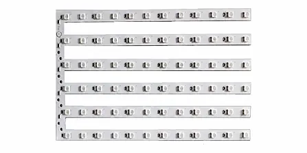
Our work extends from LED lamp beads to PCB, FPC and PCBA light source assemblies. When a project moves beyond a single emitter, the package, electrical connection and board layout can be discussed as one design task.
Configuration built around the application
Wavelength, power class, package size, die combination and structural requirements can guide a custom light-source discussion. Final operating values and deliverables are defined by the selected part and project specification.
Match the Spectrum to the Equipment

Red and near-infrared devices
Ceramic red, infrared and combined-channel examples provide starting points for equipment light-source selection. The final wavelength, irradiance, spacing and operating conditions need validation in the complete device.
Multi-color lighting
RGB and RGBW ceramic examples support discussion of independently controlled color channels, optical mixing and board connections. Select the package only after the channel map and intended lighting effect are clear.
Specialty and industrial light sources
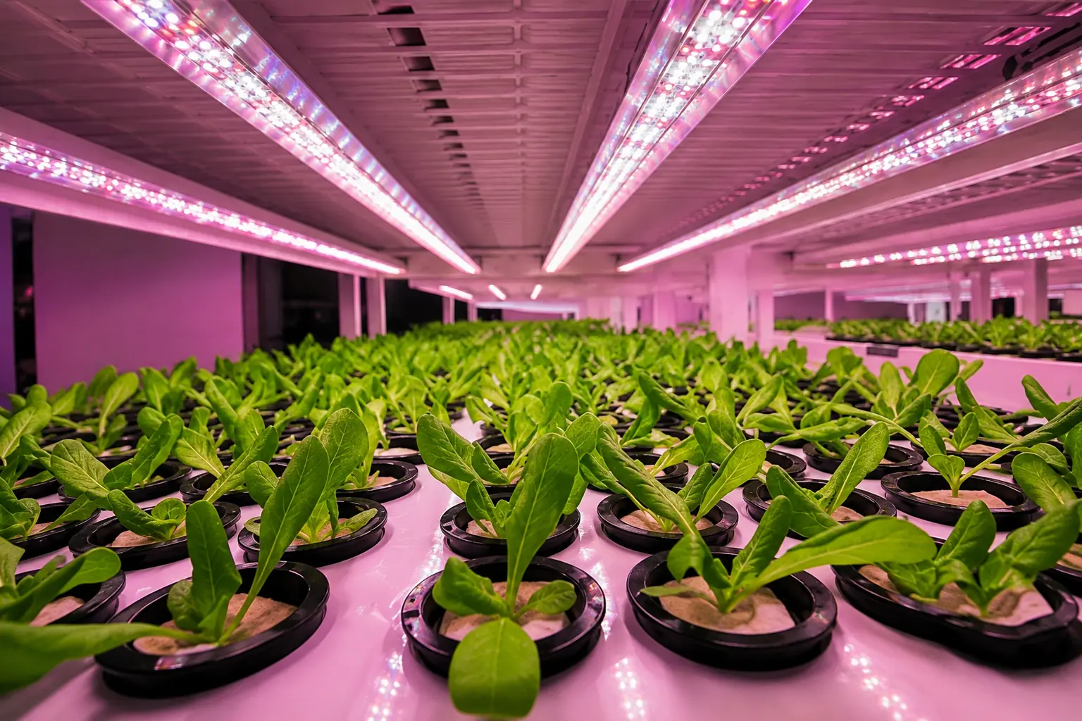
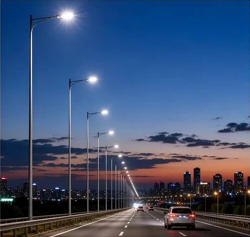
White and colored ceramic emitters can be evaluated where the package footprint, optical control and thermal design suit the equipment. Confirm the required output, environment and model-level documentation before design-in.
Ceramic High Power LED Selection Guide
What are the main advantages of a ceramic LED package?
A ceramic substrate can provide a useful route for conducting heat away from an LED die and for building a compact, high-drive package. Its practical value depends on the complete package and board design. Ceramic material alone does not establish a lower junction temperature, a longer lifetime or a higher optical output.
For Leienda’s range, the useful first decision is whether a 3535, 5050 or reviewed 6868 layout fits the available space and channel requirement. The thermal and optical result must then be evaluated using the exact part and assembly conditions.
How should ceramic and other high power LEDs be compared?
Compare like with like: the same target spectrum or color temperature, stated test current, temperature condition, optical-output unit and application geometry. Then examine the package-to-board heat path, emitting area, pad drawing, driver compatibility and the documents available for the exact part.
A non-ceramic LED can be the right choice for a different cost, space or drive target. The meaningful comparison is the performance of the selected components in the intended board and equipment, rather than a material claim applied to every LED.
Which ceramic package fits an industrial lighting design?
Begin with the fixture’s optical target and space for the emitter, optics and heat sink. A compact 3535 layout may suit a smaller source area; a 5050 or reviewed 6868 route allows a different package footprint. None of these size labels establishes suitability on its own.
For a white-light design, compare the exact part’s color temperature, output and electrical data at relevant conditions. For colored or infrared equipment, define the wavelength and optical measurement that matter to the application. Complete the decision with a board-level thermal review.
What should you check when sourcing a ceramic LED supplier?
Ask for a part-specific electrical and optical specification, package and pad drawing, channel or pin definition, test conditions and the documents relevant to your market and application. For a multi-channel part, confirm each channel separately. For a custom assembly, agree on whether the requested deliverable is the packaged emitter, a populated board or a PCBA module.
Leienda develops and produces LED lamp beads and can discuss matching board or module work. Its ISO 9001:2015 quality management certificate covers the development and production of LED lamp beads; that system certificate is distinct from a product-specific performance or compliance approval.
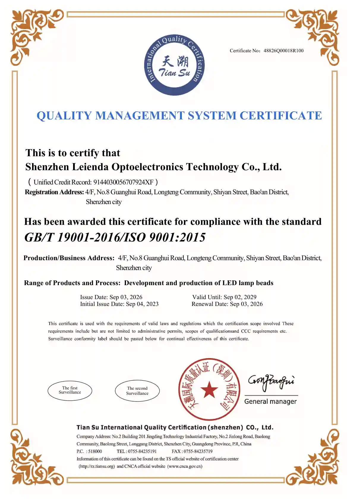
LED Lamp Bead Development and Production in Shenzhen
Leienda develops and produces LED lamp beads in Shenzhen and supports related light-source assembly work. Our ISO 9001:2015 quality management certificate identifies the development and production of LED lamp beads as its scope. Incoming-material and finished-product inspection form part of our production workflow; the inspection items for an order should be aligned with its selected part and specification.
Discuss Your Ceramic LED Specification
Tell us which package you are considering and what the light source must do in your equipment. A target wavelength or color, channel arrangement, driver conditions, board space and application drawing will help focus the discussion on a suitable part or configuration.